
Datasheet

Section 19 EEPROM
Rev.5.00 Nov. 02, 2005 Page 353 of 500
REJ09B0027-0500
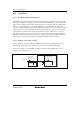
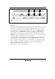
19.4.4 Stop Condition
A low-to-high transition of the SDA input with the SCL input high is needed to generate the stop
condition for stopping read, write operation.
The standby operation starts after a read sequence by a stop condition. In the case of write
operation, a stop condition terminates the write data inputs and place the device in an internally-
timed write cycle to the memories. After the internally-timed write cycle (t
WC
) which is specified
as t
WC
, the device enters a standby mode.
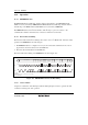
19.4.5 Acknowledge
All address data and serial data such as read data and write data are transmitted to and from in 8-
bit unit. The acknowledgement is the signal that indicates that this 8-bit data is normally
transmitted to and from.
In the write operation, EEPROM sends "0" to acknowledge in the ninth cycle after receiving the
data. In the read operation, EEPROM sends a read data following the acknowledgement after
receiving the data. After sending read data, the EEPROM enters the bus open state. If the
EEPROM receives "0" as an acknowledgement, it sends read data of the next address. If the
EEPROM does not receive acknowledgement "0" and receives a following stop condition, it stops
the read operation and enters a standby mode. If the EEPROM receives neither acknowledgement
"0" nor a stop condition, the EEPROM keeps bus open without sending read data.
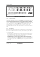
19.4.6 Slave Addressing
The EEPROM device receives a 7-bit slave address and a 1-bit R/W code following the generation
of the start conditions. The EEPROM enables the chip for a read or a write operation with this
operation.
The slave address consists of a former 4-bit device code and latter 3-bit slave address as shown in
table 19.2. The device code is used to distinguish device type and this LSI uses "1010" fixed code
in the same manner as in a general-purpose EEPROM. The slave address code selects one device
out of all devices with device code 1010 (8 devices in maximum) which are connected to the I
2
C
bus. This means that the device is selected if the inputted slave address code received in the order
of A2, A1, A0 is equal to the corresponding slave address reference register (ESAR).
The slave address code is stored in the address H'FF09 in the EEPROM. It is transferred to ESAR
from the slave address register in the memory array during 10 ms after the reset is released. An
access to the EEPROM is not allowed during transfer.