
Datasheet

Section 18 A/D Converter
Rev.5.00 Nov. 02, 2005 Page 341 of 500
REJ09B0027-0500
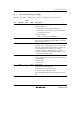
18.3.2 A/D Control/Status Register (ADCSR)
ADCSR consists of the control bits and conversion end status bits of the A/D converter.
Bit Bit Name
Initial
Value R/W Description
7 ADF 0 R/W A/D End Flag
[Setting conditions]
• When A/D conversion ends in single mode
• When A/D conversion ends once on all the channels
selected in scan mode
[Clearing condition]
• When 0 is written after reading ADF = 1
6 ADIE 0 R/W A/D Interrupt Enable
A/D conversion end interrupt request (ADI) is enabled by
ADF when this bit is set to 1
5 ADST 0 R/W A/D Start
Setting this bit to 1 starts A/D conversion. In single mode,
this bit is cleared to 0 automatically when conversion on
the specified channel is complete. In scan mode,
conversion continues sequentially on the specified
channels until this bit is cleared to 0 by software, a reset,
or a transition to standby mode.
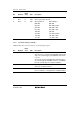
4 SCAN 0 R/W Scan Mode
Selects single mode or scan mode as the A/D conversion
operating mode.
0: Single mode
1: Scan mode
3 CKS 0 R/W Clock Select
Selects the A/D conversions time.
0: Conversion time = 134 states (max.)
1: Conversion time = 70 states (max.)
Clear the ADST bit to 0 before switching the conversion
time.