
Datasheet

Section 17 I
2
C Bus Interface 2 (IIC2)
Rev.5.00 Nov. 02, 2005 Page 310 of 500
REJ09B0027-0500
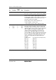
Bit Bit Name
Initial
Value R/W Description
5, 4 All 1 Reserved
These bits are always read as 1, and cannot be modified.
3 BCWP 1 R/W BC Write Protect
This bit controls the BC2 to BC0 modifications. When
modifying BC2 to BC0, this bit should be cleared to 0 and
use the MOV instruction. In clock synchronous serial
mode, BC should not be modified.
0: When writing, values of BC2 to BC0 are set.
1: When reading, 1 is always read.
When writing, settings of BC2 to BC0 are invalid.
2
1
0
BC2
BC1
BC0
0
0
0
R/W
R/W
R/W
Bit Counter 2 to 0
These bits specify the number of bits to be transferred
next. When read, the remaining number of transfer bits is
indicated. With the I
2
C bus format, the data is transferred
with one addition acknowledge bit. Bit BC2 to BC0
settings should be made during an interval between
transfer frames. If bits BC2 to BC0 are set to a value
other than 000, the setting should be made while the SCL
pin is low. The value returns to 000 at the end of a data
transfer, including the acknowledge bit. With the clock
synchronous serial format, these bits should not be
modified.
I
2
C Bus Format Clock Synchronous Serial Format
000: 9 bits 000: 8 bits
001: 2 bits 001: 1 bits
010: 3 bits 010: 2 bits
011: 4 bits 011: 3 bits
100: 5 bits 100: 4 bits
101: 6 bits 101: 5 bits
110: 7 bits 110: 6 bits
111: 8 bits 111: 7 bits