
Datasheet


Section 13 Timer Z
Rev.5.00 Nov. 02, 2005 Page 241 of 500
REJ09B0027-0500
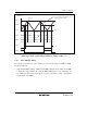
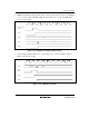
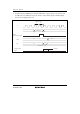
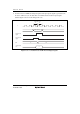
2. IMF Flag Set Timing at Input Capture: When an input capture signal is generated, the IMF flag
is set to 1 and the value of TCNT is simultaneously transferred to corresponding GR. Figure
13.49 shows the timing.
IMF
Input capture
signal
TCNT N
GR N
ITMZ
φ
Figure 13.49 IMF Flag Set Timing at Input Capture
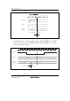
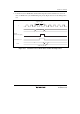
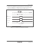
3. Overflow Flag (OVF) Set Timing: The overflow flag is set to 1 when the TCNT overflows.
Figure 13.50 shows the timing.
OVF
TCNT
Overflow
signal
H'0000H'FFFF
ITMZ
φ
Figure 13.50 OVF Flag Set Timing