
Datasheet

Section 13 Timer Z
Rev.5.00 Nov. 02, 2005 Page 213 of 500
REJ09B0027-0500
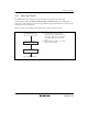
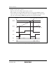
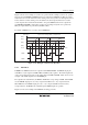
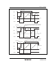
Figure 13.22 shows an example of operation in PWM mode. The output signals go to 1 and TCNT
is reset at compare match A, and the output signals go to 0 at compare match B, C, and D (TOB,
TOC, and TOD = 1, POLB, POLC, and POLD = 0).
GRA
TCNT value
Time
Counter cleared by GRA compare match
GRB
GRC
GRD
H'0000
FTIOC
FTIOD
FTIOB
Figure 13.22 Example of PWM Mode Operation (1)
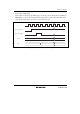
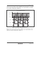
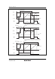
Figure 13.23 shows another example of operation in PWM mode. The output signals go to 0 and
TCNT is reset at compare match A, and the output signals go to 1 at compare match B, C, and D
(TOB, TOC, and TOD = 0, POLB, POLC, and POLD = 1).