
Datasheet


Section 13 Timer Z
TIM08Z0A_000120030300 Rev.5.00 Nov. 02, 2005 Page 175 of 500
REJ09B0027-0500
Section 13 Timer Z
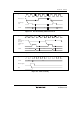
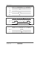
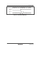
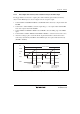
The timer Z has a 16-bit timer with two channels. Figures 13.1, 13.2, and 13.3 show the block
diagrams of entire timer Z, its channel 0, and its channel 1, respectively. For details on the timer Z
functions, refer to table 13.1.
13.1 Features
• Capability to process up to eight inputs/outputs
• Eight general registers (GR): four registers for each channel
Independently assignable output compare or input capture functions
• Selection of five counter clock sources: four internal clocks (φ, φ/2, φ/4, and φ/8) and an
external clock
• Seven selectable operating modes
Output compare function
Selection of 0 output, 1 output, or toggle output
Input capture function
Rising edge, falling edge, or both edges
Synchronous operation
Timer counters_0 and _1 (TCNT_0 and TCNT_1) can be written simultaneously.
Simultaneous clearing by compare match or input capture is possible.
PWM mode
Up to six-phase PWM output can be provided with desired duty ratio.
Reset synchronous PWM mode
Three-phase PWM output for normal and counter phases
Complementary PWM mode
Three-phase PWM output for non-overlapped normal and counter phases
The A/D conversion start trigger can be set for PWM cycles.
Buffer operation
The input capture register can be consisted of double buffers.
The output compare register can automatically be modified.
• High-speed access by the internal 16-bit bus
16-bit TCNT and GR registers can be accessed in high speed by a 16-bit bus interface
• Any initial timer output value can be set
• Output of the timer is disabled by external trigger