
Datasheet

Section 9 I/O Ports
Rev.5.00 Nov. 02, 2005 Page 111 of 500
REJ09B0027-0500
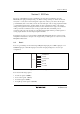
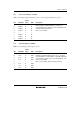
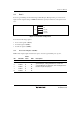
9.1.2 Port Control Register 1 (PCR1)
PCR1 selects inputs/outputs in bit units for pins to be used as general I/O ports of
port 1.
Bit Bit Name
Initial
Value R/W Description
7
6
5
4
3
2
1
0
PCR17
PCR16
PCR15
PCR14
PCR12
PCR11
PCR10
0
0
0
0
0
0
0
W
W
W
W
W
W
W
When the corresponding pin is designated in PMR1 as a
general I/O pin, setting a PCR1 bit to 1 makes the
corresponding pin an output port, while clearing the bit to
0 makes the pin an input port.
Bit 3 is a reserved bit.
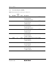
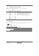
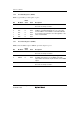
9.1.3 Port Data Register 1 (PDR1)
PDR1 is a general I/O port data register of port 1.
Bit Bit Name
Initial
Value R/W Description
7
6
5
4
3
2
1
0
P17
P16
P15
P14
P12
P11
P10
0
0
0
0
1
0
0
0
R/W
R/W
R/W
R/W
R/W
R/W
R/W
PDR1 stores output data for port 1 pins.
If PDR1 is read while PCR1 bits are set to 1, the value
stored in PDR1 are read. If PDR1 is read while PCR1 bits
are cleared to 0, the pin states are read regardless of the
value stored in PDR1.
Bit 3 is a reserved bit. This bit is always read as 1.