
Datasheet

Section 6 Power-Down Modes
Rev.5.00 Nov. 02, 2005 Page 80 of 500
REJ09B0027-0500
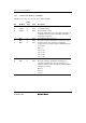
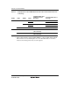
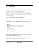
6.1.4 Module Standby Control Register 2 (MSTCR2)
MSTCR2 allows the on-chip peripheral modules to enter a standby state in module units.
Bit Bit Name
Initial
Value R/W Description
7 MSTS3_2 0 R/W SCI3_2 Module Standby
SCI3_2 enters standby mode when this bit is set to1
6, 5 All 0 Reserved
These bits are always read as 0.
4 MSTTB1 0 R/W Timer B1 Module Standby
Timer B1 enters standby mode when this bit is set to1
3, 2 All 0 Reserved
These bits are always read as 0.
1 MSTTZ 0 R/W Timer Z Module Standby
Timer Z enters standby mode when this bit is set to1
0 MSTPWM 0 R/W PWM Module Standby
PWM enters standby mode when this bit is set to1
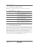
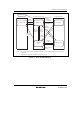
6.2 Mode Transitions and States of LSI
Figure 6.1 shows the possible transitions among these operating modes. A transition is made from
the program execution state to the program halt state by executing a SLEEP instruction. Interrupts
allow for returning from the program halt state to the program execution state. A direct transition
between active mode and subactive mode, which are both program execution states, can be made
without halting the program. The operating frequency can also be changed in the same modes by
making a transition directly from active mode to active mode, and from subactive mode to
subactive mode. RES input enables transitions from a mode to the reset state. Table 6.2 shows the
transition conditions of each mode after the SLEEP instruction is executed and a mode to return
by an interrupt. Table 6.3 shows the internal states of the LSI in each mode.