
Datasheet

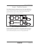

Section 5 Clock Pulse Generators
Rev.5.00 Nov. 02, 2005 Page 71 of 500
REJ09B0027-0500
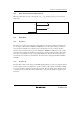
Table 5.1 Crystal Resonator Parameters
Frequency (MHz) 2 4 8 10 16 20
R
S
(max) 500 Ω 120 Ω 80 Ω 60 Ω 50 Ω 40 Ω
C
0
(max) 7 pF 7 pF 7 pF 7 pF 7 pF 7 pF
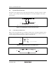
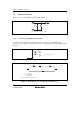
5.1.2 Connecting Ceramic Resonator
Figure 5.5 shows a typical method of connecting a ceramic resonator.
OSC
1
OSC
2
C
1
C
2
C
1
= 5 to 30 pF
C
2
= 5 to 30 pF
Figure 5.5 Typical Connection to Ceramic Resonator
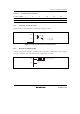
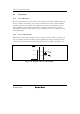
5.1.3 External Clock Input Method
Connect an external clock signal to pin OSC
1
, and leave pin OSC
2
open. Figure 5.6 shows a typical
connection. The duty cycle of the external clock signal must be 45 to 55%.
OSC
1
External clock input
OSC
2
Open
Figure 5.6 Example of External Clock Input