
Datasheet


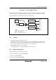


Section 14 Watchdog Timer
Rev.5.00 Nov. 02, 2005 Page 253 of 500
REJ09B0027-0500
Bit
Bit
Name Initial Value R/W Description
0 WRST 0 R/W Watchdog Timer Reset
[Setting condition]
When TCWD overflows and an internal reset signal is
generated
[Clearing conditions]
• Reset by RES pin
• When 0 is written to the WRST bit while writing 0 to the
B0WI bit when the TCSRWE bit=1
14.2.2 Timer Counter WD (TCWD)
TCWD is an 8-bit readable/writable up-counter. When TCWD overflows from H'FF to H'00, the
internal reset signal is generated and the WRST bit in TCSRWD is set to 1. TCWD is initialized to
H'00.
14.2.3 Timer Mode Register WD (TMWD)
TMWD selects the input clock.
Bit Bit Name
Initial
Value R/W Description
7 to 4 All 1 Reserved
These bits are always read as 1.
3
2
1
0
CKS3
CKS2
CKS1
CKS0
1
1
1
1
R/W
R/W
R/W
R/W
Clock Select 3 to 0
Select the clock to be input to TCWD.
1000: Internal clock: counts on φ/64
1001: Internal clock: counts on φ/128
1010: Internal clock: counts on φ/256
1011: Internal clock: counts on φ/512
1100: Internal clock: counts on φ/1024
1101: Internal clock: counts on φ/2048
1110: Internal clock: counts on φ/4096
1111: Internal clock: counts on φ8192
0XXX: Internal oscillator
For the internal oscillator overflow periods, see section
23, Electrical Characteristics.
Legend: X: Don't care.