
User's Manual


1
Section 1 Configuration
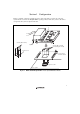
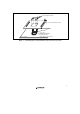
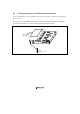
Figure 1 and table 1 show the external appearance and components, respectively, of the user
system interface board for the PLQP0144KA-A package. Please make sure you have all of these
components after you have unpacked the box.
Evaluation-chip board
Spacer
User system
interface board
User system
IC socket
Screws (M2 × 10 mm)
(for fastening the board)
Screws (M2 × 6 mm)
Socket cover
Figure 1 H8SX/1668R PLQP0144KA-A User System Interface Board