
User`s manual


14
11 SFR used by the program for the E8 emulator
The SFR listed in Table 5.4 is used by the program for the E8 emulator as well as the user program. Do not change
the value in the memory window, etc., by other than the user program.
The SFR listed in Table 5.5 is used by the program for the E8 emulator, not user program. Do not change the
registers, otherwise the E8 cannot be controlled.
The SFRs listed in Table 5.4 and 5.5 are not initialized by selecting [Debug] -> [Reset CPU] or with the RESET
command. If their contents are referred to, a value that has been set in the program for the E8 emulator will be read.
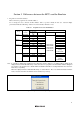
Table 5.4 SFR Used by Program for E8 Emulator (1)
Address Register Symbol Bit
0006h System clock control register 0 CM0 Bit 6
0007h System clock control register 1 CM1 Bits 4, 6 and 7
0008h High-speed on-chip oscillator control register 0 HR0 Bits 0 and 1
000Ah Protect register PRCR Bits 0 and 1
000Bh High-speed on-chip oscillator control register 1 HR1 All bits
000Ch Oscillation stop detection register OCD Bit 2
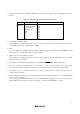
Table 5.5 SFR Used by Program for E8 Emulator (2)
Address Register Symbol Bit
Notes on using
the E8 emulator
00A8h UART1 transmit/receive mode register U1MR All bits *1
00A9h UART1 bit rate register U1BRG All bits *1
00AAh, 00ABh UART1 transmit buffer register U1TB All bits *1
00ACh UART1 transmit/receive control register 0 U1C0 All bits *1
00ADh UART1 transmit/receive control register 1 U1C1 All bits *1
00AEh, 00AFh UART1 receive buffer register U1RB All bits *1
00B0h UART transmit/receive control register 2 UCON Bits 1, 5 and 6 *2
*1 Do not change the value of the register.
*2 Do not change the value of the bits listed above. When operating this register, change it by a bit operating
instruction, etc.
12. Interrupts used by the E8 emulator program
The BRK instruction interrupt, address match interrupt and single-step interrupt are used by the E8 emulator
program. Therefore, make sure the user program does not use these interrupts.
13. Peripherals used by the E8 emulator program
UART1 is used by the E8 emulator. Do not use UART1 by the user program.
14. Reserved area
The addresses not specified in the Hardware Manual for R8C/10, R8C/11, R8C/12 and R8C/13 Groups are reserved
area. Do not change the contents. Otherwise, the E8 emulator cannot be controlled.
15. Debugging in the stop mode or wait mode
When using the stop mode or wait mode on a user program, firstly disable the automatic update in the watch
window or fix the display in the memory window so that the memory access will not occur during execution. In
addition, do not operate the window until the program stops at the breakpoint by setting the breakpoint at the
processing unit where the stop mode or wait mode is cancelled.