
User`s manual


13
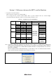
3. When the emulator system is initiated, it initializes the general registers and part of the control registers as shown in
Table 5.3.
Table 5.3 Register Initial Values at Emulator Power-On
Status Register Initial Value
PC Reset vector value in the vector address table
R0 to R3 (bank 0, 1) 0000h
A0, A1 (bank 0, 1) 0000h
FB (bank 0, 1) 0000h
INTB 0000h
USP 0000h
ISP 05FFh
SB 0000h
Emulator
Power-On
FLG 0000h
4. Operation clock during a break
As the emulator is controlled independent of a user’s system clock during a user program break, it operates with the
internal high-speed on-chip oscillator (approx. 8 MHz).
5. Reset
To reset the MCU when debugging by the E8 emulator, select [Debug] -> [Reset CPU] or use the RESET command.
If the emulator is reset differently, the E8 cannot be controlled.
6. Memory access during emulation execution
When referring or modifying the memory contents, the user program is temporarily halted. For this reason, realtime
emulation cannot be performed.
7. The emulator communicates with the MCUs by using the MODE, RESET
, P00, P37 and CNVss pins.
8. The power consumed by the MCU increases by several mA or over 10 mA. This is because the user power supply
drives one 74LVC125A to make the communication signal level match the user-system power-supply voltage.
9. The emulator uses up to four-word stack pointer when a user program breaks. Accordingly, reserve the four-word
addresses for the stack area.
10. When debugging, the flash memory is frequently re-written by the E8 emulator. Therefore, do not use an MCU that
has been used for debugging.
Also, as the program for the E8 emulator is written into the MCU while debugging, do not save the contents of the
MCU’s flash memory that have been used for debugging or use them as the ROM data for products.