
User`s manual


10
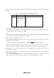
8. Figure 4.6 shows the interface circuit in the E8 emulator. Use this figure as a reference when determining
the pull-up resistance value.
P37
CNVss
74LVC125A
Vcc
MODE
RESET
Emulator control circuit
User system connector
7
13
8
74LVC125A
100kΩ
10kΩ
11
1
100kΩ
1MΩ
100kΩ
5
P00
*
22Ω
22Ω
22Ω
22Ω
22Ω
* Power of the upper 74LVC125A is supplied from Vcc in the user system connector.
Figure 4.6 Interface Circuit in the Emulator (Reference)