
User`s manual


9
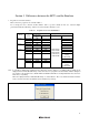
4. The RESET pin is used by the E8 emulator. Create the following circuit by connecting the open-collector
output buffer so that reset input can be accepted from the E8 emulator.
RESET
User
logic
Vcc
*
Pulled-up at
4.7kΩ or more
*: Open-collector buffer
R8C/13
R8C/12
R8C/11
R8C/10
RESET
User system
connector
13
Figure 4.5 Example of a Reset Circuit
5. Connect Vss and Vcc with the Vss and Vcc of the MCU, respectively.
6. Connect nothing with N.C.
7. The amount of voltage permitted to input to Vcc must be within the guaranteed range of the microcomputer.