
User`s manual


8
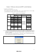
Notes: 1. P00 and P37 pins are used by the E8 emulator. Pull up and connect the emulator and MCU pins.
P00/TxD11
P37/RxD1
R8C/13
R8C/12
R8C/11
R8C/10
P00
P37
Vcc
Vcc
Pulled-up at
4.7kΩ or more
User system
connector
5
11
Figure 4.2 Connection of E8 Emulator and MCU
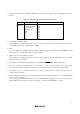
2. The E8 emulator uses the MODE pin for the MCU control and the forced break control. Connect the E8
emulator to the MCU pins through pull-up.
MODE
R8C/13
R8C/12
R8C/11
R8C/10
MODE
Vcc
Pulled-up at
4.7kΩ or more
User system
connector
7
Figure 4.3 Connection of E8 Emulator and MODE Pin
3. The E8 emulator uses the CNVss pin for the MCU control and communication. Connect the E8 emulator to
the MCU pins through pull-down.
CNVss
R8C/13
R8C/12
R8C/11
R8C/10
CNVss
Pulled-down at
4.7kΩ or more
User system
connector
1
Figure 4.4 Connection of E8 Emulator and CNVss Pin