
User`s manual


5
Section 3 Pin Assignments of the E8 Connector
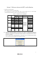
Figure 3.1 shows the pin assignments of the connector.
Pin 1 mark
Pin 2
Pin 1 mark
Connector
Pin NO.
R8C/10, 11, 12, 13
MCU signals
1 CNVss
2Vss
3N.C.
4Vss
5P00/AN7/TxD11
6Vss
7 MODE
8Vcc
9N.C.
10 Vss
11 P37/TxD10/RxD1
12 Vss
13 RESET
14 Vss
Pin 1
Pin 14
Pin 13
Figure 3.1 Pin Assignments of the E8 Connector