
User`s manual


3
Section 2 Connecting the Emulator with the User System
Before connecting an E8 emulator (hereafter referred to as emulator) with the user system, a connector must be
installed in the user system so that a user system interface cable can be connected. When designing the user system,
refer to Figure 3.1, Pin Assignments of the E8 Connector, and Figure 4.1, Example of E8 Connection, shown in this
manual.
Before designing the user system, be sure to read the E8 emulator user’s manual and the hardware manual for related
MCUs.
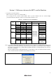
Table 2.1 shows the recommended connector for the emulator.
Table 2.1 Recommended Connector
Type Number Manufacturer Specifications
2514-6002 3M Limited 14-pin straight type
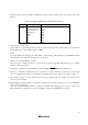
Connect pins 2, 4, 6, 10, 12, and 14 of the user system connector to GND firmly on the PCB. These pins are used as
electrical GND and to monitor the connection of the user system connector. Note the pin assignments of the user
system connector.
Pin 1
Pin 2
User system
Connector
User system interface cable
Figure 2.1 Connecting the User System Interface Cable to the User System
Notes: 1. Do not place any components within 3 mm of the connector.
2. When the emulator is used in the writer mode, connect the emulator similarly to the user system.