
User`s manual


Chapter 8.Programming Methods
All of the Flash ROM on the device (i.e. both MATs) can be programmed when the device is in Boot mode. Once in boot mode, the
boot-loader program pre-programmed into the microcontroller executes and attempts a connection with a host (for example a PC). On
establishing a connection with the microcontroller, the host may then transmit program data to the microcontroller via the appropriate
programming port.
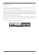
Table 8-1 below shows the programming port for this Renesas Microcontroller and its associated pins
Programming Port Table – Programming port pins and their CPU board signal names
SCI4 TXD4, PIN 5 RXD4, PIN 7 SCK4, PIN 8
CPU board Signal Name PTTX PTRX PTCK
Table 8-1: Serial Port Boot Channel
8.1.Serial Port Programming
This sequence is not required when debugging using the E8 supplied with the kit.
The microcontroller must enter boot mode for programming, and the programming port must be connected to a host for program download.
To execute the boot transition, and allow programs to download to the microcontroller, the user must perform the following procedure:
Connect a 1:1 serial cable between the host PC and the CPU board
Depress the BOOT switch and keep this held down
Depress the RESET switch once, and release
Release the BOOT switch
The Flash Development Toolkit (FDT) is supplied to allow programs to be loaded directly on to the board using this method.
8.2.E10A Header
This device supports an optional E10A debugging interface. The E10A provides additional debugging features including hardware
breakpoints and hardware trace capability. (Check with the website at
www.renesas.com or your distributor for a full feature list).
To utilise the E10A the user will need to fit a 14 way boxed header to J7. To enable the E10A functions the user should also fit a jumper link
in position J6.
When J6 is fitted the microcontroller will not operate correctly unless operated via the E10A.
19