
User`s manual


6.7.Oscillator Sources
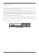
A crystal oscillator is fitted on the CPU board and used to supply the main clock input to the Renesas microcontroller. Table 6-8 details
the oscillators that are fitted and alternative footprints provided on this CPU board:
Component
Value : Package Manufacturer
Approved See www.renesas.com for details Crystal (X1) Fitted 6MHz : HC/49U
CPU board Magna Frequency Components
C-Mac
X6M0GCBE494SM*
LFXTAL017159
Table 6-8: Oscillators / Resonators
Warning: When replacing the default oscillator with that of another frequency, the debugging monitor will not function unless the following
are corrected:
• FDT programming kernels supplied are rebuilt for the new frequency
• The supplied HMON debugging monitor is updated for baud rate register settings.
The user is responsible for code written to support operating speeds other than the default. See the HMON User Manual for details of
making the appropriate modifications in the code to accommodate different operating frequencies.
6.8.Reset Circuit
The CPU Board includes a simple latch circuit that links the mode selection and reset circuit. This provides an easy method for swapping
the device between Boot Mode, User Boot Mode and User mode. This circuit is not required on customers boards as it is intended for
providing easy evaluation of the operating modes of the device on the RSK. Please refer to the hardware manual for more information on
the requirements of the reset circuit.
The reset circuit operates by latching the state of the boot switch on pressing the reset button. This control is subsequently used to modify
the mode pin states as required.
The mode pins should change state only while the reset signal is active to avoid possible device damage.
The reset is held in the active state for a fixed period by a pair of resistors and a capacitor. Please check the reset requirements carefully to
ensure the reset circuit on the user’s board meets all the reset timing requirements.
14