
User`s manual


6.5.LCD Module
A LCD module can be connected to the connector J13. Any module that conforms to the pin connections and has a KS0066u compatible
controller can be used with the tutorial code. The LCD module uses a 4bit interface to reduce the pin allocation. No contrast control is
provided; this must be set on the display module.
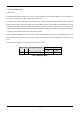
Table 6-5 shows the pin allocation and signal names used on this connector.
The module supplied with the CPU board only supports 5V operation.
J13
Pin Circuit Net Name Device
Pin
Pin Circuit Net Name Device
Pin
1 Ground - 2 5V Only -
3 No Connection - 4 DLCDRS 51
5 R/W (Wired to Write only) - 6 DLCDE 55
7 No Connection - 8 No connection -
9 No Connection - 10 -
11 DLCD4 68 12 DLCD5 67
13 DLCD6 66 14 DLCD7 61
Table 6-5 LCD Module Connections
12