
Hardware manual


25
After short description of all registers we can shortly explain how PWM works inside H8S/2638.
So, at the beginning, user has to select which PWM he is going to use. He also needs to set up
proper polarity default it is set as direct. Then, using PWCR we need to select proper clock
source for example which is the fastest one. Next step is to set PWM frequency with help of
PWCYR. When we do all of these we can switch on the counter using once again PWCR.
The question which arises now is how PWM outputs are set up? This can be very easily
presented on following pictures nr 4.2-3 and nr 4.2-4:
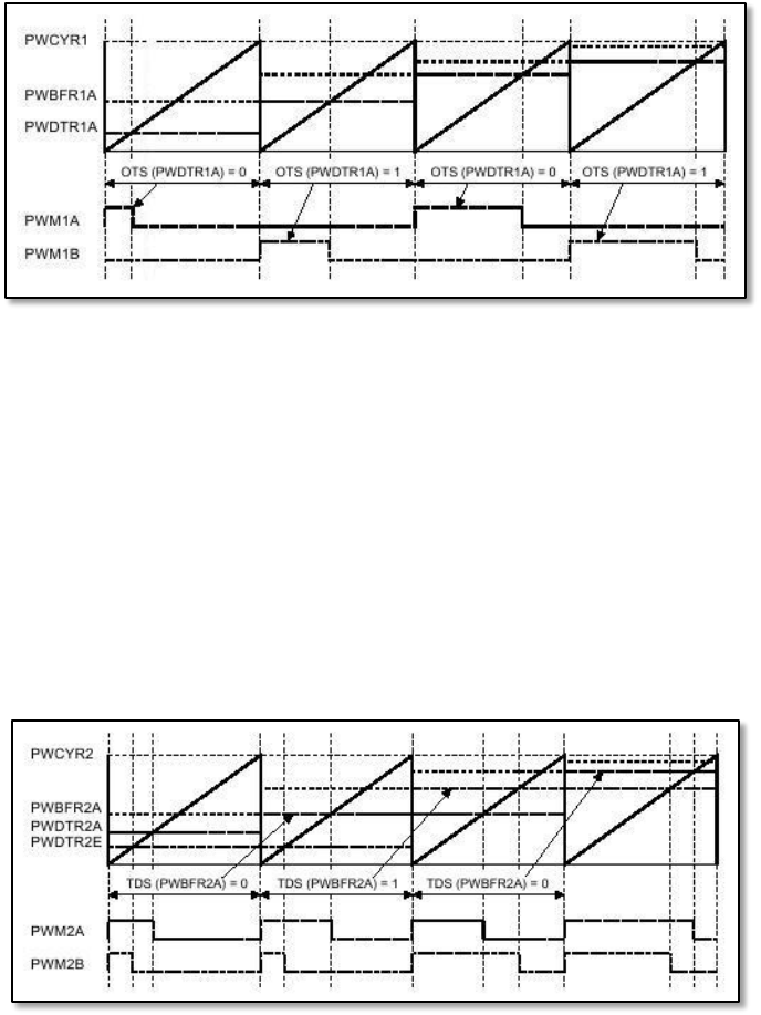
Fig. 4.2-3. Output on the PWM channel 1 during compare matching.
Figure 4.2-3 presents first channel which is described in the following lines. At the beginning of
the PWM period, data from buffer register PWBFR1A is transferred to duty register PWDTR1A.
Just after that, PWM unit checks OTS bits. If it is low or equal to 0, high state of the output is
present on PWM1A output. If OTS is high or equal to 1, high state is put to PWM1B. This high
state is kept till compare match between counter and PWDTR1A occurs. In other words, we can
say that till value of the counter is bellow value of PWDTR1A, the output of proper PWM1 is
kept high. In the same time when counter is incremented, we can put new value to buffer
register PWBFR1A. When the next period starts value of that register will be shifted to
PWDTR1A and the whole process will repeat.
Fig. 4.2-4. Output on the PWM channel 2 during compare matching.