
Hardware manual


24
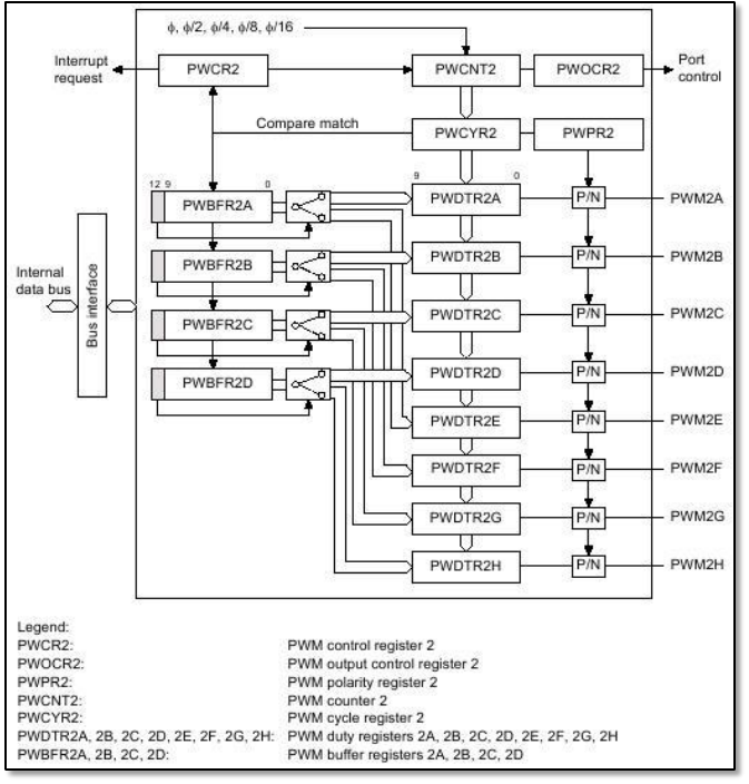
Fig. 4.2-2. PWM channel 2 in H8S/2638.
PWMOCR1 and PWMOCR2 are used to select which PWM outputs should be enabled and which
should be disabled. Selecting proper bits we can enable or disable corresponding PWM output.
PWPR1 and PWPR2 are useful for changing polarity of PWM outputs. Polarity can be direct or
inverse. Thanks PWCR1 and PWCR1 we can decide whether the PWCNT counter is enabled or
not. The same register allows us also to select the clock for corresponding channel. We can
choose: , /2, /4, /8 or /16, where is an internal frequency of the microcontroller.
Registers called PWCYR1 and PWCYR2 are PWM conversion cycles and they describe when data
from buffer register should be transferred to the duty registers (we can think about it as PWM
frequency). PWCNT1 and PWCNT2 are two 10-bit up-counters. We can't influence them directly.
They are incremented by the input clock and are used to make several comparisons described
later. PWBFR1 (A, C, E, G) and PWBFR2 (A to D) are buffer registers. We can put here 10-bits
values which will be later transferred to the duty registers. Selecting 12
th
bits OTS or TDS
respectively for 1
st
and 2
nd
channel we can choose to which PWM (1
st
channel) or duty register
(2
nd
channel) data should be transferred. PWDTR1 (A, C, E, G) and PWDTR2 (A to H) are so called
duty registers. These registers can't be read or write directly and values present inside them are
transferred during compare match from proper PWBFRxx registers.