
Hardware manual


19
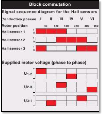
Fig. 3.5-2. Position of the motor and
reading from HAL sensor.
I think it is good idea to explain little bit how we can rotate the motor in desired direction using
table presented on the figure 3.5-2. Thus, if we know from hall sensors that we are in phase I
and we want to rotate the motor into one direction all we need is just to apply positive or
negative voltages according to values shown in the table. In other words for phase I we need to
keep some positive voltage difference between 1
st
and 2
nd
windings, and the same time zero
voltage difference between 2
nd
and 3
rd
and between 3
rd
and 1
st
windings (first column in the
table). If we would like to rotate the motor into opposite direction, then we need to keep
negative voltage difference between 1
st
and 2
nd
windings, and as before zero voltage difference
between 2
nd
and 3
rd
and between 3
rd
and 1
st
windings (fourth column in the table). According to
this we can say that the change in the direction of rotation corresponds to applying inverted
voltages or using voltages which should be applied after reading hall sensor and adding 180
o
. Of
course we should remember that after some time the value read from hall senor will change and
to continue of the rotation we will have to set new voltage differences between windings
according to table on the fig. 3.5-2.
3.6. Putting everything together.
In this subsection I will shortly describe how all presented above was taken and put together to
get right working motor in Eurobot project.