
Hardware manual


16
At this point small explanation about IRC and its channels should be given. Firstly couple of
words about IRC. IRC is just a rotary and relative sensor which works in a similar way as was
described in previous paragraph. Secondly we need to ask about one essential thing. How do we
know in which direction our motor is rotating? The answer to this question may get closer if we
look at the following graph 3.4-2:
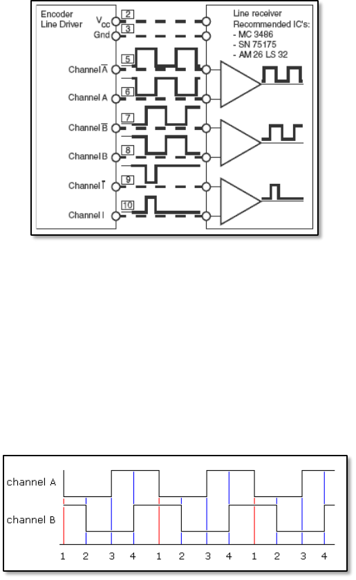
Fig. 3.4-2. Pulses generated in channels during rotation.
This picture presents basically how connections are made in the IRC and what kind of the output
they give. What is important for us at the moment is the small difference between the output
from the channel A and the channel B. Yes, it is not mistake. Namely, when the motor is
rotating, these two channels have 90
o
difference in phase and knowing this difference we are
able to find out the direction of the rotation. This property can be also used to explain why we
are using 4 in the next subsection, in the example with calculation of the phase table length.
now at the following figure:
Fig. 3.4-3. Outputs from channels A and B during rotation.
The basic explanation of above graph is that both channels have some differences in phase and
during one cycle we can detect exactly 4 combinations of the outputs. TPU unit in
microcontroller can be set to phase shift counting mode what allows to count the number of
displacement between edges. And what does it give us? Yes, exactly as it was written in
description of the incremental encoder it gives relative position and speed. More detailed
explanation of the phase shift counting mode can be found in next chapter in the subsection
concerned with