
Hardware manual


13
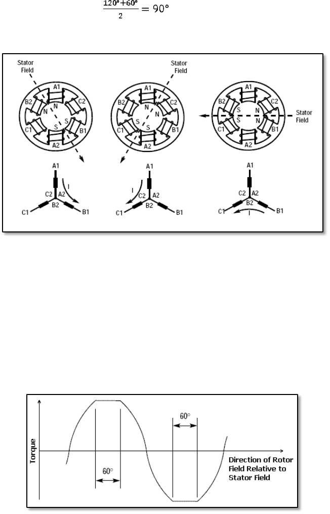
Explanation of this figure is quite short and easy. As we know from previous pictures, we
consider situation when we have only three phases. This means we can move stator filed only
with resolution of 60
o
. start with a difference in angle between the rotor and the stator
field equal to 120
o
and wait till the rotor rotates by 60
o
. As the result we will get the difference
equal only to 60
o
. At the same time we change the stator field direction by 60
o
in the rotation
direction what gives us as a result the situation analogical to the initial conditions. The most
important now is that the average difference in the above is 90
o
. This can be very easily
calculated in following manner: . The final result is almost exactly what we
wanted. Below picture presents the rotor position at different commutation points.
Fig. 3.2-5. Rotor position at commutation point.
Now as I promised at the beginning of this section, we will look shortly and try to explain the
basic differences between a trapezoidal and a sin wave motor.
start with the trapezoidal motor. When a current has fixed level in the windings (for
example 3A), then the use of the sinusoidal torque characteristic provides to a large degree of
torque ripple. To minimize this unwanted effect we can flatten the torque characteristic and
make it similar to the trapezoidal. The example of it can be seen on the following picture:
Fig. 3.2-6. Trapezoidal characteristic of a torque.