
Hardware manual


12
The above presented differences in arrangement change the speed and torque inversely
proportional to the factor of: . Of course the arrangement of the windings doesn't have crucial
rule in the motor selection.
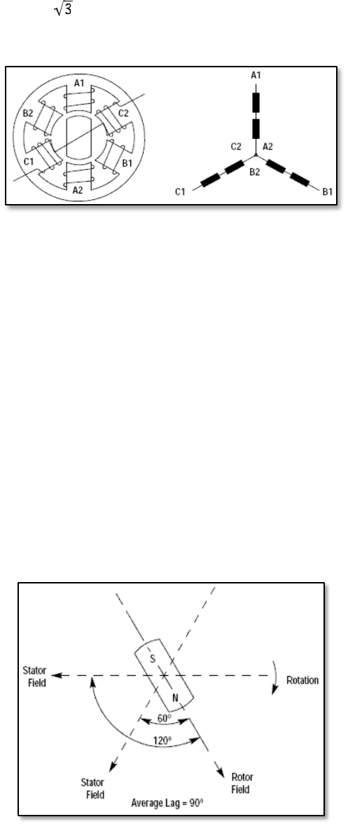
Fig.3.2-3. Coils and poles inside brushless motor.
As presented on the figure nr 3.2-3 as a typical brushless motor has three sets of coils called
This motor has also 2 poles. In normal case the rotor has four or six poles with
corresponding higher number of stator poles. Mentioned here the increase in the number of
poles doesn't have influence to the number of phases.
We know from the basic physics that the torque is at the maximum when the magnetic field is
perpendicular to the object on which we want to act. Due to this rule, we always try to set the
stator field and rotor at 90
o
degree each other. Now, to keep the torque as constant we should
always keep above angle at 90
o
. Looking at schematics on the picture nr 3.2-3 we find out that if
we are able only to switch phase voltages on and off it is impossible for us to meet above
mentioned condition. This is due to the limit in the number of phases. In above example we
have 3 phases so the minimal resolution is 60
o
degree and only by this minimal value we can
change the stator field direction. Hopefully, there exists small trick which we can use to be very
close to 90
o
. The basic graphical idea is presented on the following picture nr 3.2-4:
Fig. 3.2-4. Stator and rotor magnetic field.