
User`s manual


Table Of Contents
- This is the safety alert symbol. It is used to alert you to potential personal injury hazards. Obey all safety messages that follow this symbol to avoid possible injury or death.
- 2238.pdf
- Preface
- Section 1Configuration
- Section 2Connection Procedures
- Section 3Installing the MCU to the User System
- Section 4Verifying Operation
- Section 5Notice
Section 4 Verifying Operation
1. When using the E6000 emulator for the H8S/2633 series, turn on the emulator according to the
procedures described in the H8S/2633 E6000 Emulator User's Manual (HS2633REPI61HE).
2. Verify the user system interface cable connections by accessing the external memory and ports
to check the bus states of the pins with the MEMORY_FILL command (emulator command). If
an error is detected, recheck the soldered IC socket and the location of pin 1.
3. The emulator connected to this user system interface cable supports two kinds of clock sources
as the MCU clock: an emulator internal clock and an external clock on the user system. For
details, refer to the H8S/2633 E6000 Emulator User's Manual (HS2633REPI61HE).
To use the emulator internal clock
Select the clock in the emulator station with the [CLOCK] option in the [Configuration
Properties] dialog box.
To use the external clock on the user system
Select external clock (target or target/2) with the [CLOCK] option in the [Configuration
Properties] dialog box, and supply the external clock from the user system to the emulator.
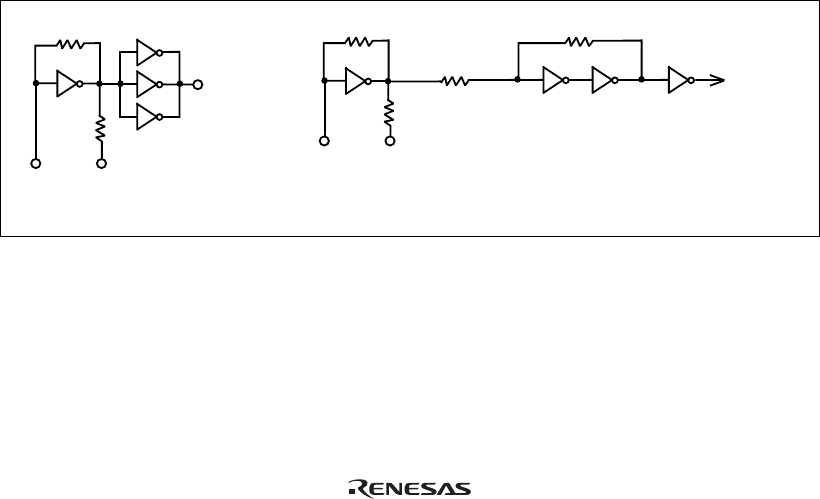
Supply the external clock to the system clock by inputting the external clock from the
EXTAL terminal on the cable head or connecting a crystal oscillator to the EXTAL and
XTAL terminals. To supply the external clock to the subclock, connect the 32.768-kHz
crystal oscillator to the OSC1 and OSC2 terminals. The user system interface cable has the
oscillator circuits shown in figure 10. For details, refer to section 22, Clock Pulse Generator,
in the H8S/2238R Series, H8S/2237 Series Hardware Manual.
14
R2 270 Ω
R1 1 MΩ
HCU04
HCU04
To E6000
emulator
EXTAL XTAL
System clock oscillator
R6 470 k
R5 3.3 M
HCU04
HCU04 HCU04
To E6000
emulator
OSC1 OSC2
Subclock oscillator
Ω
Ω
R12 2.2 kΩ
R13 10 kΩ
Figure 10 Clock Oscillator Circuits