H8S/2214 Series TBP-112 User System Interface Cable (HS2214ECB61H) for E6000 Emulator User’s Manual HS2214ECB61HE(C)
Cautions 1. Renesas neither warrants nor grants licenses of any rights of Renesas’s or any third party’s patent, copyright, trademark, or other intellectual property rights for information contained in this document. Renesas bears no responsibility for problems that may arise with third party’s rights, including intellectual property rights, in connection with use of the information contained in this document. 2. Products and product specifications may be subject to change without notice.
Preface Thank you for purchasing this user system interface cable (HS2214ECB61H) for the Renesas’s original microcomputer H8S/2214series. The HS2214ECB61H is a user system interface cable that connects an H8S/2214 series E6000 emulator (HS2214EPI61H; hereinafter referred to as the emulator) to the IC socket for a TBP-112 package for the H8S/2214 series MCU on the user system.
Contents Section 1 Configuration....................................................................................1 Section 2 Connection Procedures ......................................................................3 2.1 2.2 2.3 2.4 2.5 Connecting User System Interface Cable to Emulator Station ......................................... 3 Connecting User System Interface Cable to User System ................................................ 5 2.2.1 Soldering the IC Socket ............................
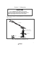
Section 1 Configuration CAUTION Use an CSPACK112A1110H01 socket (socket (manufactured by Tokyo Eletech Corporation) for the TBP-112 package IC socket on the user system. Figure 1 shows the configuration of the HS2214ECB61H user system interface cable for the TBP-112 package. To emulator station Cable body Screws (M1.
Table 1 lists the HS2214ECB61H components. Please make sure you have all of these components when unpacking. Table 1 HS2214ECB61H Components No. Component Quantity Remarks Includes flat cable 1 Cable body 1 2 Cable head 1 3 IC socket 1 For the TBP-112 package 4 Spacer 1 For installing an TBP-112 packaged MCU 5 Cover 1 For installing an TBP-112 packaged MCU 6 Screws (M1.
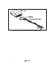
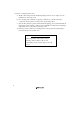
Section 2 Connection Procedures 2.1 Connecting User System Interface Cable to Emulator Station WARNING Observe the precautions listed below. Failure to do so will result in a FIRE HAZARD and will damage the user system and the emulator product or will result in PERSONAL INJURY. The USER PROGRAM will be LOST. 1. Always switch OFF the user system and the emulator product before the USER SYSTEM INTERFACE CABLE is connected to or removed from any part.
Figure 2 Connecting User System Interface Cable to Emulator Station 4
2.2 Connecting User System Interface Cable to User System WARNING Always switch OFF the user system and the emulator product before the USER SYSTEM INTERFACE CABLE is connected to or removed from any part. Before connecting, make sure that pin 1 on both sides are correctly aligned. Failure to do so will result in a FIRE HAZARD and will damage the user system and the emulator product or will result in PERSONAL INJURY. The USER PROGRAM will be LOST.
(4) Notes on soldering the IC socket a) The IC socket is larger than the actual IC package; therefore, refer to figure 7 for the installation of other components. b) Do not install components that occupy large volume close to the IC socket. Such components will prevent the convective flow of heat during reflow.
CAUTION 1. Never dip the IC socket in flux or use wash to clean the IC socket. This is because flux may remain inside the IC socket due to the IC socket’s structure. When using the IC socket with other DIP products, never clean the other DIP products with flux because the flux may enter the connector through the guide pins of the IC socket. 2. When an IC socket with guide pins is soldered to the user system, about 1.4 mm of the guide pins will stick out (when the user-system board is 1.6 mm thick).
2.2.2 Inserting Cable Head CAUTION Check the location of pin 1 before inserting. Align pin 1 on the IC socket for an TBP-112 package on the user system with pin 1 on the user system interface cable head, and insert the user system interface cable head into the IC socket on the user system, as shown in figure 3.
2.2.3 Fastening Cable Head CAUTION 1. Use the screwdriver whose head matches the screw head. 2. The tightening torque must be 0.054 N•m or less. If the applied torque cannot be accurately measured, stop tightening when the force required to turn the screw becomes significantly greater than that needed when first tightening. If a screw is tightened too much, the screw head may break or an IC socket contact error may be caused by a crack in the IC socket solder. 3.
2. Next, fasten screws to ② and ④ a little, so that four screw holes are aligned. Then, each screw should be tightened a little at a time, alternating between screws on opposing corners.
2.2.4 Fastening Cable Body Connect the cable body to the cable head.
2.3 Recommended Dimensions for User System Mount Pad Figure 7 shows the recommended dimensions for the mount pad (footprint) for the user system with an IC socket for an TBP-112 package (CSPACK112A1110H01: socket (manufactured by Tokyo Eletech Corporation). Note that the dimensions in figure 7 are somewhat different from those of the actual chip's mount pad.
2.4 Dimensions for User System Interface Cable Head The dimensions for the user system interface cable head are shown in figure 8.
2.5 Resulting Dimensions after Connecting User System Interface Cable The resulting dimensions, after connecting the user system interface cable head to the user system, are shown in figure 9.
Section 3 Installing the MCU to the User System CAUTION 1. Check the location of pin 1 before inserting. 2. Use a provided screwdriver. 3. The tightening torque must be 0.054 N•m or less. If the applied torque cannot be accurately measured, stop tightening when the force required to turn the screw becomes significantly greater than that needed when first tightening. If a screw is tightened too much, the screw head may break or an IC socket contact error may be caused by a crack in the IC socket solder. 4.
Figure 10 Installing MCU to User System 16
Section 4 Verifying Operation 1. When using the E6000 emulator for the H8S/2214 series, turn on the emulator according to the procedures described in the H8S Series E6000 Emulator User's Manual (HS2000EPI61HE). 2. Verify the user system interface cable connections by accessing the external memory and ports to check the bus states of the pins with the MEMORY_FILL command (emulator command). If an error is detected, recheck the soldered IC socket and the location of pin 1. 3.
Section 5 Notice 1. Make sure that pin 1 on the user system IC socket is correctly aligned with pin 1 on the cable head before inserting the cable head into the user system IC socket. 2. The dimensions of the recommended mount pad for the user system IC socket are different from those of the MCU. 3. This user system interface cable is specifically designed for the HS2214EPI61H emulator. Do not use this cable with any other emulator station. 4.