
H8S/2100 Series H8S Family Models H8S/2111B Group Hardware Manual

Rev. 1.00, 05/04, page 296 of 544
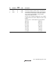
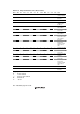
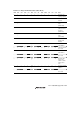
Table 13.5 Flags and Transfer States (Slave Mode) (cont)
MST TRS BBSY ESTP STOP IRTR AASX AL AAS ADZ ACKB ICDRF ICDRE State
0 0 1 0 0 — — — — — — 1 — Reception end with
ICDRF=1
0 0 1 0 0 — — 0↓ 0↓ 0↓ — 0↓ — ICDR read with the
above state
0 0 1 0 0 1↑/0
*
2
— 0 0 0 — 1↑ — Automatic data
transfer from
ICDRS to ICDRR
with the above
state
0 — 0↓ 1↑/0
*
3
0/1↑
*
3
— — — — — — — 0↓ Stop condition
detected
[Legend]
0: 0-state retained
1: 1-state retained
—: Previous state retained
0
↓: Cleared to 0
1
↑: Set to 1
Notes: 1. Set to 1 when 1 is received as a R/W bit following an address.
2. Set to 1 when the AASX bit is set to 1.
3. When ESTP = 1, STOP is 0, or when STOP = 1, ESTP is 0.