
User`s manual


HokutoElectronic FLASH1 User’s Manual
-7-
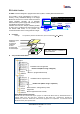
Signal-name of Required RS232C Straight Cable
Caution! :The no.4 & 5 lines of the programmer side must be connected appropriately, because
of the importance for the steady control form “FLASH1 for Windows”.
Signals Between FLASH1 and Target Board
FLASH1 side Target board side
Signal name Pin number
Directions
Signal name Pin number
1
GND
2 GND GND 1
3 RXD TXD 2
4 TX RXD 3
5 RESET
RES
4
6 VIN USERVCC 5
7 FVPP Vpp 6
8 MD MD 7
9 GND GND 8
10 GND
Cable-connector-type-name between Target Board and FLASH1
※OKI・・・OKI Electric Cable Company, Limited
. Both OKI (Electric Cable Company,lmd) are MIL standard box connectors.
Red line is1P
RS232C
FLASH1
JAE IL-S-8S-S2C2-S
JAE IL-S-8P-S2L2-EF
OKI FL10A2F0-KN
OKI FL10A2MA
Target Board
USER VCC is consumed
about 10mA at FLASH1.
DOS/V series with 9 pins connector
PC
programmer
9pins 25pins
2 2
3 3
4 4
5 5
6 6
7 7
8 20
PC9801with 25 pins connector
PC
programmer
25pins 25pins
1 1
2 2
3 3
4 4
5 5
6 6
7 7
20 20