
Technical data


FIRE Emulator for H8S and H8/300H 16 General SYStem Settings and Restrictions
©1989-2014 Lauterbach GmbH
General SYStem Settings and Restrictions
General Restrictions
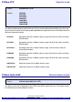
SYStem.Option V33 3.3 V power fail detection
The emulator has a detection logic to detect a target power fail. This option must be set to on, if a 3.3V target
is used.
Onchip DTC-RAM The CPUs onchip DTC-RAM is physically internal at the bondout
chip. The write accesses of the CPU to the DTC area are shadowed
to an emulator RAM, so that this shadow DTC-RAM can be read via
dual-port, but there is no dualport write-access available to the DTC
area.
The CPU uses a 32-bit data transfer for reading and writing DTC
register information, but only the lower 16 bit of the data can be seen
in the trace (restriction of the bondout chip).
BurstROM interface The BurstROM interface can’t be mapped as internal. The on-chip
breakpoints must be used for the runtime control in an external
BurstRom area.
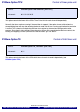
Interrupt requests dur-
ing the emulation is
stopped
Exceptions and interrupts are not handled during the emulation is
stopped. Some of them are stored and executed after starting the
emulation (see chapter Exception Control). If you will have
problems with either your target hardware or you application
program because of the blocked interrupts, then you have to use a
foreground monitor.
Pending interrupts dur-
ing single-step
When executing an assembler step and external or internal
interrupts are pending, the emulator will step into the interrupt
handler and stops at the first instruction of the interrupt service
routine. The execution of the interrupt program can be avoided
either by preventing the interrupt, e.g. stop the timer while the
emulation is stopped (see timer control) or by masking the interrupt
in the CPU (command SETUP.IMASKASM). For HLL steps the
problem can be solved in the same way (command
SETUP.IMASKHLL).
Format: SYStem.Option V33 [ON | OFF]