H8/3257 Series, H8/325 Series FP-64A User System Interface Cable (HS3257ECH61H) for E6000 Emulator User’s Manual ADE-xxx-xxx Rev. 3.0 4/1/03 Renesas Technology Corp.
Cautions 1. Renesas neither warrants nor grants licenses of any rights of Renesas’s or any third party’s patent, copyright, trademark, or other intellectual property rights for information contained in this document. Renesas bears no responsibility for problems that may arise with third party’s rights, including intellectual property rights, in connection with use of the information contained in this document. 2. Products and product specifications may be subject to change without notice.
Preface Thank you for purchasing the E6000 emulator for the Renesas’s original microprocessor H8/300 series. The HS3257ECH61H is a user system interface cable that connects an H8/300 series E6000 emulator (HS3008EPI60H; hereinafter referred to as the emulator) to the IC socket for a FP-64A package for the H8/3257 series, H8/325 series MCU on the user system.
Contents Section 1 Configuration.....................................................................................1 Section 2 Connection Procedures ......................................................................3 2.1 2.2 2.3 2.4 2.5 Connecting User System Interface Cable to Emulator Station ......................................... 3 Connecting User System Interface Cable to User System ................................................ 4 2.2.1 Installing IC Socket ................................
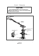
Section 1 Configuration CAUTION Use an IC149-064-008-B5 socket (manufactured by YAMAICHI ELECTRONICS Co., Ltd.) for the FP-64A package IC socket on the user system. Figure 1 shows the configuration of the HS3257ECH61H user system interface cable for the FP-64A package Screws (M2.0 x 12 mm) and flat washers (For fastening cable head) Screws (M2.
Table 1 lists the HS3257ECH61H components. Please make sure you have all of these components when unpacking. Table 1 HS3257ECH61H Components No. Component Quantity Remarks 1 Cable body 1 Includes cables 2 Cable head 1 3 IC socket 1 For the FP-64A package 4 Socket cover 1 For installing an FP-64A-packaged MCU 5 Screws (M2.0 x 12 mm) 4 For fastening cable head (with four flat washers) 6 Screws (M2.
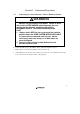
Section 2 Connection Procedures 2.1 Connecting User System Interface Cable to Emulator Station WARNING Observe the precautions listed below. Failure to do so will result in a FIRE HAZARD and will damage the user system and the emulator product or will result in PERSONAL INJURY. The USER PROGRAM will be LOST. 1. Always switch OFF the user system and the emulator product before the USER SYSTEM INTERFACE CABLE is connected to or removed from any part.
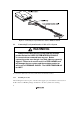
Figure 2 Connecting User System Interface Cable to Emulator Station 2.2 Connecting User System Interface Cable to User System WARNING Always switch OFF the user system and the emulator product before the USER SYSTEM INTERFACE CABLE is connected to or removed from any part. Before connecting, make sure that pin 1 on both sides are correctly aligned. Failure to do so will result in a FIRE HAZARD and will damage the user system and the emulator product or will result in PERSONAL INJURY.
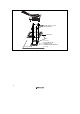
2.2.2 Soldering IC Socket After fastening, solder the IC socket for an FP-64A package to the user system. Be sure to completely solder the leads so that the solder slops gently over the leads and forms solder fillets. (Use slightly more solder than the MCU.) 2.2.3 Inserting Cable Head CAUTION Check the location of pin 1 before inserting.
Screws (M2.0 x 12 mm) and flat washers Cable head Pin 1 User system IC socket (IC149-064-008-B5 manufactured by YAMAICHI ELECTRONICS Co., Ltd.
2.2.5 Fastening Cable Body Connect the cable body to the cable head.
2.3 Recommended Dimensions for User System Mount Pad Figure 5 shows the recommended dimensions for the mount pad (footprint) for the user system with an IC socket for an FP-64A package (IC149-064-008-B5: manufactured by YAMAICHI ELECTRONICS Co., Ltd.). Note that the dimensions in figure 5 are somewhat different from those of the actual chip's mount pad. 20.80 min 14.80 max 0.80 x 15 = 12.00 ± 0.10 + 0.10 Unit: mm Figure 5 Recommended Dimensions for Mount Pad 8 0.80 x 15 = 12.00 ± 0.10 0.45 - 0.05 0.
2.4 Dimensions for User System Interface Cable Head The dimensions for the user system interface cable head are shown in figure 6.
2.5 Resulting Dimensions after Connecting User System Interface Cable 9.4 The resulting dimensions, after connecting the user system interface cable head to the user system, are shown in figure 7. User system IC socket (IC149-064-008-B5 manufactured by YAMAICHI ELECTRONICS Co., Ltd.) Unit: mm Tolerance: ± 0.
Section 3 Installing the MCU to the User System CAUTION 1. Check the location of pin 1 before inserting. 2. Use a Phillips-type screwdriver whose head matches the screw head. 3. The tightening torque must be 0.0784 N•m or less. If the applied torque cannot be accurately measured, stop tightening when the force required to turn the screw becomes significantly greater than that needed when first tightening.
Socket cover MCU Pin 1 mark User system IC socket (IC149-064-008-B5 manufactured by YAMAICHI ELECTRONICS Co., Ltd.
Section 4 Verifying Operation 1. When using the H8/300 series E6000 emulator (HS3008EPI60H), turn on the emulator according to the procedures described in the H8/300 Series E6000 Emulator User's Manual (HS3008EPI60HE). 2. Verify the user system interface cable connections by accessing the external memory and ports to check the bus states of the pins. If an error is detected, recheck the soldered IC socket and the location of pin 1. 3.
Section 5 Notice 1. Make sure that pin 1 on the user system IC socket is correctly aligned with pin 1 on the cable head before inserting the cable head into the user system IC socket. 2. The dimensions of the recommended mount pad for the user system IC socket are different from those of the MCU. 3. This user system interface cable is specifically designed for the HS3008EPI60H emulator. Do not use this cable with any other emulator station. 4.