
Hardware manual


Rev. 3.0, 09/98, page 69 of 361
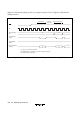
IRQ flag
IRQ 0E
ADF
ADIE
CPU
I (CCR)
NMI interrupt
Interrupt
controller
IRQ0
interrupt
Interrupt request
Vector number
ADI
interrupt
Priority
decision
Note: * For edge-sensed interrupts, these AND gates change to the circuit shown below.
*
IRQ0 edge
IRQ0 E
SQ
IRQ0 flag
IRQ0 interrupt
Figure 4.3 Block Diagram of Interrupt Controller
The IRQ interrupts and interrupts from the on-chip supporting modules all have corresponding
enable bits. When the enable bit is cleared to “0,” the interrupt signal is not sent to the interrupt
controller, so the interrupt is ignored. These interrupts can also all be masked by setting the
CPU’s interrupt mask bit (I) to “1.” Accordingly, these interrupts are accepted only when their
enable bit is set to “1” and the I bit is cleared to “0.”
The nonmaskable interrupt (NMI) is always accepted, except in the reset state and hardware
standby mode.
When an NMI or another enabled interrupt is requested, the interrupt controller transfers the
interrupt request to the CPU and indicates the corresponding vector number. (When two or more
interrupts are requested, the interrupt controller selects the vector number of the interrupt with the
highest priority.) When notified of an interrupt request, at the end of the current instruction or
current hardware exception-handling sequence, the CPU starts the hardware exception-handling
sequence for the interrupt and latches the vector number.
Figure 4.4 is a flowchart of the interrupt (and reset) operations. Figure 4.6 shows the interrupt
timing sequence for the case in which the software interrupt-handling routine is in on-chip ROM
and the stack is in on-chip RAM.