
Hardware manual


Rev. 3.0, 09/98, page 68 of 361
4.3.3 External Interrupts
The nine external interrupts are NMI and IRQ
0
to IRQ
7
. NMI, IRQ
0
, IRQ
1
, and IRQ
2
can be used
to recover from software standby mode.
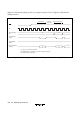
(1) NMI: A nonmaskable interrupt is generated on the rising or falling edge of the NMI input
signal regardless of whether the I (interrupt mask) bit is set in the CCR. The valid edge is selected
by the NMIEG bit in the system control register. The NMI vector number is 3. In the NMI
hardware exception-handling sequence the I bit in the CCR is set to “1.”
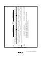
(2) IRQ
0
to IRQ
7
: These interrupt signals are level-sensed or sensed on the falling edge of the
input, as selected by ISCR bits IRQ
0
SC to IRQ
7
SC. These interrupts can be masked collectively
by the I bit in the CCR, and can be enabled and disabled individually by setting and clearing bits
IRQ
0
E to IRQ
7
E in the IRQ enable register.
When one of these interrupts is accepted, the I bit is set to “1.” IRQ
0
to IRQ
7
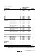
have interrupt vector
numbers 4 to 11. They are prioritized in order from IRQ
7
(Low) to IRQ
0
(High). For details, see
table 4.2.
Interrupts IRQ
0
to IRQ
7
do not depend on whether pins IRQ
0
to IRQ
7
are input or output pins.
When using external interrupts IRQ
0
to IRQ
7
, clear the corresponding DDR bits to “0” to set these
pins to the input state, and do not use these pins as input or output pins for the timers, serial
communication interface, or A/D converter.
4.3.4 Internal Interrupts
Twenty-two internal interrupts can be requested by the on-chip supporting modules. Each
interrupt source has its own vector number, so the interrupt-handling routine does not have to
determine which interrupt has occurred. All internal interrupts are masked when the I bit in the
CCR is set to “1.” When one of these interrupts is accepted, the I bit is set to 1 to mask further
interrupts (except NMI). The vector numbers are 12 to 35. For the priority order, see table 4.2.
4.3.5 Interrupt Handling
Interrupts are controlled by an interrupt controller that arbitrates between simultaneous interrupt
requests, commands the CPU to start the hardware interrupt exception-handling sequence, and
furnishes the necessary vector number. Figure 4.3 shows a block diagram of the interrupt
controller.