
Hardware manual


Rev. 3.0, 09/98, page 63 of 361
A
15
to A
0
RD
WR
D
7
to D
0
(8 bits)
Ø
RES
(2) (4) (6) (8)
(1)
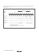
Vector fetch
(1),(3) Reset vector address: (1)=H'0000, (3)=H'0001
(2),(4) Starting address of program (contents of reset vector): (2)=upper byte, (4)=lower byte
(5),(7) Starting address of program: (5)=(2)(4), (7)=(2)(4)+1
(6),(8) First instruction of program: (6)=first byte, (8)=second byte
Instruction prefetch
Internal
processing
(3) (5) (7)
Figure 4.2 Reset Sequence (Mode 1)