
Hardware manual


Rev. 3.0, 09/98, page 18 of 361
“0” otherwise. Similarly, it is set to “1” when the ADD.W, SUB.W, or CMP.W instruction causes
a carry or borrow out of bit 11, and cleared to “0” otherwise. It is used implicitly in the DAA and
DAS instructions.
Bit 4User Bit (U): This bit can be written and read by software (using the LDC, STC, ANDC,
ORC, and XORC instructions).
Bit 3Negative Flag (N): This flag indicates the most significant bit (sign bit) of the result of an
instruction.
Bit 2Zero Flag (Z): This flag is set to “1” to indicate a zero result and cleared to “0” to
indicate a nonzero result.
Bit 1Overflow Flag (V): This flag is set to “1” when an arithmetic overflow occurs, and
cleared to “0” at other times.
Bit 0Carry Flag (C): This flag is used by:
•
Add and subtract instructions, to indicate a carry or borrow at the most significant bit of the
result
•
Shift and rotate instructions, to store the value shifted out of the most significant or least
significant bit
•
Bit manipulation and bit load instructions, as a bit accumulator
The LDC, STC, ANDC, ORC, and XORC instructions enable the CPU to load and store the CCR,
and to set or clear selected bits by logic operations. The N, Z, V, and C flags are used in
conditional branching instructions (B
CC
).
For the action of each instruction on the flag bits, see the H8/300 Series Programming Manual.
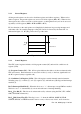
2.2.3 Initial Register Values
When the CPU is reset, the program counter (PC) is loaded from the vector table and the interrupt
mask bit (I) in the CCR is set to “1.” The other CCR bits and the general registers are not
initialized.
In particular, the stack pointer (R7) is not initialized. To prevent program crashes the stack pointer
should be initialized by software, by the first instruction executed after a reset.