
Hardware manual


Rev. 3.0, 09/98, page 14 of 361
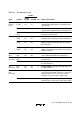
Table 1.3 Pin Functions (cont)
Pin No.
Type Symbol
CG-84
CP-84 FP-80A I/O Name and Function
General-
purpose
I/O
P1
7
to P1
0
71 to 78 57 to 64 I/O Port 1: An 8-bit input/output port with
programmable MOS input pull-ups and LED
driving capability. The direction of each bit can
be selected in the port 1 data direction register
(P1DDR).
P2
7
to P2
0
61 to 63,
65 to 69
48 to 55 I/O Port 2: An 8-bit input/output port with
programmable MOS input pull-ups and LED
driving capability. The direction of each bit can
be selected in the port 2 data direction register
(P2DDR).
P3
7
to P3
0
3, 1,
84 to 79
72 to 65 I/O Port 3: An 8-bit input/output port with
programmable MOS input pull-ups. The
direction of each bit can be selected in the port
3 data direction register (P3DDR).
P4
7
to P4
0
59 to 52 46 to 39 I/O Port 4: An 8-bit input/output port. The
direction of each bit can be selected in the port
4 data direction register (P4DDR).
P5
2
to P5
0
20 to 22 9 to 11 I/O Port 5: A 3-bit input/output port. The direction
of each bit can be selected in the port 5 data
direction register (P5DDR).
P6
7
to P6
0
40 to 33 28 to 21 I/O Port 6: An 8-bit input/output port. The
direction of each bit can be selected in the port
6 data direction register (P6DDR).
P7
7
to P7
0
50 to 43 37 to 30 I Port 7: An 8-bit input port.
P8
6
to P8
0
11 to 5 80 to 74 I/O Port 8: A 7-bit input/output port. The direction
of each bit can be selected in the port 8 data
direction register (P8DDR).
P9
7
to P9
0
25 to 32 13 to 20 I/O Port 9: An 8-bit input/output port. The
direction of each bit (except for P96) can be
selected in the port 9 data direction register
(P9DDR).