
Hardware manual


Rev. 3.0, 09/98, page 13 of 361
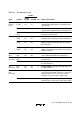
Table 1.3 Pin Functions (cont)
Pin No.
Type Symbol
CG-84
CP-84 FP-80A I/O Name and Function
FTOA,
FTOB
34
39
22
27
O FRT Output compare A and B: Output pins
controlled by comparators A and B of the free-
running timer.
16-bit free-
running
timer
FTCI 33 21 I FRT counter Clock Input: Input pin for an
external clock signal for the free-running timer.
FTIA to
FTID
35 to 38 23 to 26 I FRT Input capture A to D: Input capture pins
for the free-running timer.
8-bit timer TMO
0
,
TMO
1
53
56
40
43
O 8-bit Timer Output (channels 0 and 1):
Compare-match output pins for the 8-bit timers.
TMCI
0
,
TMCI
1
52
55
39
42
I 8-bit Timer counter Clock Input (channels 0
and 1): External clock input pins for the 8-bit
timer counters.
TMRI
0
,
TMRI
1
54
57
41
44
I 8-bit Timer counter Reset Input (channels 0
and 1): A High input at these pins resets the 8-
bit timer counters.
PWM
timer
PW
0
,
PW
1
58
59
45
46
O PWM timer output (channels 0 and 1):
Pulse-width modulation timer output pins.
AN
7
to
AN
0
50 to 43 37 to 30 I Analog input: Analog signal input pins for the
A/D converter.
A/D
converter
ADTRG 32 20 I A/D Trigger: External trigger input for starting
the A/D converter.
D/A
converter
DA
0
DA
1
49
50
36
37
O Analog output: Analog signal output pins for
the D/A converter.
AV
CC
42 29 I Analog reference Voltage: Reference voltage
pin for the A/D and D/A converters. If the A/D
and D/A converters are not used, connect
AVCC to the system power supply (+5V).
A/D and
D/A
converters
AV
SS
51 38 I Analog ground: Ground pin for the A/D and
D/A converters.Connect to system ground (0V).