
Hardware manual


Rev. 3.0, 09/98, page 148 of 361
7.4.2 Output Compare Timing
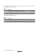
(1) Setting of Output Compare Flags A and B (OCFA and OCFB): The output compare flags
are set to “1” by an internal compare-match signal generated when the FRC value matches the
OCRA or OCRB value. This compare-match signal is generated at the last state in which the two
values match, just before the FRC increments to a new value.
Accordingly, when the FRC and OCR values match, the compare-match signal is not generated
until the next period of the clock source. Figure 7.7 shows the timing of the setting of the output
compare flags.
H' 0000
N
Internal compare-
match A signal
Ø
FRC
Figure 7.7 Setting of Output Compare Flags
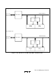
(2) Output Timing: When a compare-match occurs, the logic level selected by the output level
bit (OLVLA or OLVLB) in TOCR is output at the output compare pin (FTOA or FTOB).
Figure 7.8 shows the timing of this operation for compare-match A.
Ø
Internal input
capture signal
Input at FTI pin
Figure 7.8 Timing of Output Compare A