H8/36014 Group, H8/36024 Group FP-64E User System Interface Cable for E6000 Emulator User’s Manual HS36014ECH61H Renesas Microcomputer Development Environment System Rev.2.00 2003.12.
Cautions Keep safety first in your circuit designs! 1. Renesas Technology Corp. puts the maximum effort into making semiconductor products better and more reliable, but there is always the possibility that trouble may occur with them. Trouble with semiconductors may lead to personal injury, fire or property damage.
IMPORTANT INFORMATION READ FIRST • READ this user's manual before using this user system interface cable. • KEEP the user's manual handy for future reference. Do not attempt to use the user system interface cable until you fully understand its mechanism. User System Interface Cable: Throughout this document, the term "user system interface cable" shall be defined as the following product produced only by Renesas Technology Corp. excluding all subsidiary products.
LIMITED WARRANTY Renesas warrants its user system interface cables to be manufactured in accordance with published specifications and free from defects in material and/or workmanship. Renesas will repair or replace any user system interface cables determined to be defective in material and/or workmanship. User system interface cables are wearing parts which Renesas will not repair or replace if damaged and/or worn through use.
State Law: Some states do not allow the exclusion or limitation of implied warranties or liability for incidental or consequential damages, so the above limitation or exclusion may not apply to you. This warranty gives you specific legal rights, and you may have other rights which may vary from state to state.
SAFETY PAGE READ FIRST • READ this user's manual before using this user system interface cable. • KEEP the user's manual handy for future reference. Do not attempt to use the user system interface cable until you fully understand its mechanism. DEFINITION OF SIGNAL WORDS This is the safety alert symbol. It is used to alert you to potential personal injury hazards. Obey all safety messages that follow this symbol to avoid possible injury or death.
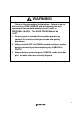
WARNING Observe the precautions listed below. Failure to do so will result in a FIRE HAZARD and will damage the user system and the emulator product or will result in PERSONAL INJURY. The USER PROGRAM will be LOST. 1. Do not repair or remodel the emulator product by yourself for electric shock prevention and quality assurance. 2. Always switch OFF the E6000 emulator and user system before connecting or disconnecting any CABLES or PARTS. 3.
Preface Thank you for purchasing this user system interface cable (HS36014ECH61H) for the Renesas’s original microcomputer H8/36014 series. The HS36014ECH61H is a user system interface cable that connects an H8/36014 series E6000 emulator (HS3664EPI61H; hereinafter referred to as the emulator) to the IC socket for an FP-64E package for the H8/36014 series MCU on the user system and to the H8/36024 series expansion I/O board (HS36024EIO61H).
Contents Section 1 Configuration....................................................................................1 Section 2 Connection Procedures ......................................................................3 2.1 2.2 2.3 2.4 2.5 2.6 Connecting User System Interface Cable to Emulator Station (H8/36014 Series)............ 3 Connecting User System Interface Cable to Expansion I/O Board (H8/36024 Series)..... 5 Connecting User System Interface Cable to User System..............................
Section 1 Configuration CAUTION Use an IC149-064-075-B51 socket (manufactured by YAMAICHI ELECTRONICS Co., Ltd.) for the FP-64E package IC socket on the user system. Figure 1 shows the configuration of the HS36014ECH61H user system interface cable for the FP-64E package.
Table 1 lists the HS36014ECH61H components. Please make sure you have all of these components when unpacking. Table 1 HS36014ECH61H Components No.
Section 2 Connection Procedures 2.1 Connecting User System Interface Cable to Emulator Station (H8/36014 Series) WARNING Observe the precautions listed below. Failure to do so will result in a FIRE HAZARD and will damage the user system and the emulator product or will result in PERSONAL INJURY. The USER PROGRAM will be LOST. 1. Always switch OFF the user system and the emulator product before the USER SYSTEM INTERFACE CABLE is connected to or removed from any part.
Figure 2 Connecting User System Interface Cable to Emulator Station 4
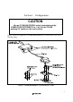
2.2 Connecting User System Interface Cable to Expansion I/O Board (H8/36024 Series) WARNING Always switch OFF the user system and the emulator product before the USER SYSTEM INTERFACE CABLE is connected to or removed from any part. Before connecting, make sure that pin 1 on both sides are correctly aligned. Failure to do so will result in a FIRE HAZARD and will damage the user system, the emulator product, and the expansion I/O board or will result in PERSONAL INJURY. The USER PROGRAM will be LOST.
E60 TO ULA EM 0 0 0 6 00 E Expansion I/O board cable ABL EC FAC ER ER US INT Cable body connector CTS screws (M3 x 6 mm) User system interface cable Figure 3 Connecting User System Interface Cable to Expansion I/O Board 6
2.3 Connecting User System Interface Cable to User System WARNING Always switch OFF the user system and the emulator product before the USER SYSTEM INTERFACE CABLE is connected to or removed from any part. Before connecting, make sure that pin 1 on both sides are correctly aligned. Failure to do so will result in a FIRE HAZARD and will damage the user system and the emulator product or will result in PERSONAL INJURY. The USER PROGRAM will be LOST.
2.3.3 Inserting Cable Head CAUTION Check the location of pin 1 before inserting. Align pin 1 on the IC socket for an FP-64E package on the user system with pin 1 on the user system interface cable head, and insert the user system interface cable head into the IC socket on the user system, as shown in figure 4. 2.3.4 Fastening Cable Head CAUTION 1. Use a Philips-type screwdriver whose head matches the screw head. 2. The tightening torque must be 0.13 N•m or less.
Fasten the user system interface cable head to the IC socket for an FP-64E package on the user system with the four screws (M2 x 12 mm; with four flat washers) provided. Each screw should be tightened a little at a time, alternating between screws on opposing corners. Take special care, such as manually securing the IC socket soldered area, to prevent the soldered IC socket from being damaged by overtightening the screws or twisting the components.
2.3.5 Fastening Cable Body Connect the cable body to the cable head.
2.4 Recommended Dimensions for User System Mount Pad Figure 6 shows the recommended dimensions for the mount pad (footprint) for the user system with an IC socket for an FP-64E package (IC149-064-075-B51: manufactured by YAMAICHI ELECTRONICS Co., Ltd.). Note that the dimensions in figure 6 are somewhat different from those of the actual chip's mount pad.
2.5 Dimensions for User System Interface Cable Head The dimensions for the user system interface cable head are shown in figure 7.
2.6 Resulting Dimensions after Connecting User System Interface Cable The resulting dimensions, after connecting the user system interface cable head to the user system, are shown in figure 8.
Section 3 Installing the MCU to the User System CAUTION 1. Check the location of pin 1 before inserting. 2. Use a Philips-type screwdriver whose head matches the screw head. 3. The tightening torque must be 0.29 N•m or less. If the applied torque cannot be accurately measured, stop tightening when the force required to turn the screw becomes significantly greater than that needed when first tightening.
Figure 9 Installing MCU to User System 15
Section 4 Verifying Operation 1. When using the H8/36014 series E6000 emulator (HS3664EPI61H), turn on the emulator according to the procedures described in the H8/300H Series E6000 Emulator User's Manual (HS300HEPI61HE). 2. Verify the user system interface cable connections by accessing ports and checking the bus states of the pins. If an error is detected, recheck the soldered IC socket and the location of pin 1. 3.
Figure 10 shows the system clock oscillator on the user system interface cable.
Section 5 Notice 1. Make sure that pin 1 on the user system IC socket is correctly aligned with pin 1 on the cable head before inserting the cable head into the user system IC socket. 2. The dimensions of the recommended mount pad for the user system IC socket are different from those of the MCU. 3. This user system interface cable is specifically designed for the HS3644EPI61H emulator. Do not use this cable with any other emulator station. 4.
6. The P1 short connector is used for testing. Do not remove the inserted jumper pin.
H8/36014 Group, H8/36024 Group FP-64E User System Interface Cable for E6000 Emulator User's Manual Publication Date: Rev.1.00, March 18, 2002 Rev.2.00, December 19, 2003 Published by: Sales Strategic Planning Div. Renesas Technology Corp. Edited by: Technical Documentation & Information Department Renesas Kodaira Semiconductor Co., Ltd. 2002, 2003 Renesas Technology Corp. All rights reserved.
H8/36014 Group, H8/36024 Group FP-64E User System Interface Cable for E6000 Emulator User’s Manual REJ10B0091-0200H