
Instruction manual
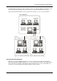


Designing and Planning an M2150 System
Access Control Design Guide
37
Installation Requirements
Before installing an M2150 system, all installers should be made aware of the following.
UL Requirements
Ensure that all installers are familiar with UL installation requirements, as given in Appendix B on page 54.
Shielded Cable (Screens)
To avoid multiple paths to ground, cable shields must be connected only as shown in the installation
instructions. If the shield is shown unconnected at one end of the cable, it must be insulated to prevent
accidental shorting to the case, PCB tracks, etc. Each cabinet must connect to ground.
Electrical Codes
All cables and wiring must be completed in accordance with appropriate codes of practice, e.g. the US
National Electrical Code, NFPA 70, and any local authority requirements.
Cable Clips
All wiring should be routed neatly to the relevant terminal blocks and fixed in position using cable clips. The
cable clips can be fixed to the base or sides of the cabinet.
Preparing for the Site Visit
Before visiting the site, installers should make sure that:
• The appropriate Installation instructions and Access Control Design Guide are available. The latest
versions of these publications can be obtained from the AMAG web site. See page v for a list of
publications.
• All appropriate equipment specified on the Site Schematic is available.
• The SMS software and sentinels are available for installation, if appropriate.
• Other contractors have completed any work that is required before installation can begin (for
example, installation of auxiliary equipment).
• A standard set of tools is available. No specialist tools are required.
• Suitable supplies of the following are available:
Cable.
Cable clips.
Minitrunking or plastic tubing.
Sleeving for shields (screens).
Grommets (glands) for entry of cables into the cabinet.
Door furniture (door-monitor contacts, exit-request push buttons and door releases).
Screws and wall plugs.
Spare fuses (see page 44).
9-way or 25-way connectors for connections to PC or modems, if required.
Ethernet cable for RJ-45 connection to NIC module, if required.
Termination resistors and enclosures for cable supervision (see page 31), if required.
Crimp connectors for grounding.