
Instruction manual


Designing and Planning an M2150 System
Access Control Design Guide
15
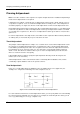
floor is in the card holder's access rights, the appropriate floor relay in the node is de-energized
(COM to NC contacts made) and further transactions are inhibited for the length of time specified by
the reader's Floor Selection Time.
Note: In the SMS Software, the elevator node Floor Selection option must be set to Individual to
activate Enable Select mode.
Enable All Mode
Enable All Mode requires no wiring between the elevator interface board and floor buttons, but since
the node cannot know which floor button was selected, it reports only that the card holder was
granted access at the elevator reader.
After a valid access-control transaction, the elevator node de-energizes all floor relays that
correspond to the floors in the card holder's access rights. The relays are de-energized (COM to NC
contacts made) and further card transactions are inhibited for the length of time specified by the
Floor Selection Time option in the elevator reader's Reader Definitions screen in the SMS software.
Note: In the SMS Software, the elevator node Floor Selection option must be set to None to
activate Enable All mode.
Cable Requirements
Plan the cable requirements carefully. In particular, determine the length and number of cables needed in
the traveling cable – refer to Table 2-2.
Table 2-5 on page 30 gives the maximum distances for cabling. Make sure these distances will not be
exceeded, then mark on the Site Schematic the routes to be taken by cables to the elevator nodes.
Table 2-2: Cables Required for the Traveling Cable
Cables Required in Traveling Cable?
Description Elevator Node in Equipment
Room
Elevator Node on Elevator
Cab
Reader connections Yes No
Node power No Site dependent
Node communications No Yes
Floor buttons Yes
(1)
No
Floor relays Yes Site dependent
Fireman's Switch No Yes
(1)
Enable Select mode only; not used in Enable All operation.