
Instruction manual


Designing and Planning an M2150 System
Access Control Design Guide
11
Note:
• Antipassback can have an impact on the number of database units required. If the site is to use
antipassback rules, please refer to the section on page 20.
• Each elevator to be access controlled requires a separate DBU in an elevator node (see page 14).
Specifying the Address of a Door or Alarms Controller
Each door and alarms controller connected to the same database unit must have a unique address, which
should be marked on the Site Schematic. The installation instructions for the door and alarms controllers
describe how to set the controller address.
The door/alarms controller address can be:
• Between 1 and 8 when connected to a DBU.
• Between 2 and 8 when connected to a 2DBC (integrated controller occupies address 1).
• Between 3 and 8 when connected to a 4DBC (integrated controller occupies addresses 1 and 2).
• Between 5 and 8 when connected to a 8DBC (integrated controller occupies addresses 1, 2, 3 and
4).
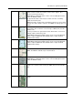
The number of addresses occupied by each controller is as follows:
• AC24/4 or OC4/24 – 2 addresses. If, for example, you set an AC24/4 to address 5, it occupies
addresses 5 and 6. This device can have address 1, 3, 5 or 7 only (depending on the database unit).
• 2DC – 1 address.
• 4DC/4DCN – 2 addresses. This device can have address 1, 3, 5 or 7 only (depending on the
database unit).
• 8DC – 4 addresses. This device can have address 1 or 5 only.
Specifying the Database Unit Communications Options (Port Usage)
This section explains how to specify the communications method that each database unit will use to
communicate with an SMS PC and other optional devices.
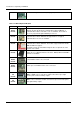
Each database unit has an integrated RS232 port (COM C) for communications with the SMS PC, ENVS
or other serial device controlled by the SMS software. There are two additional ports (COM D and COM E),
each of which can be fitted with a NIC4, NIC-WI or one-port RS232 module. The NIC4 module allows wired
network communications to the SMS PC; the NIC-WI is used for wireless network communications, and
the one-port RS232 module allows connection to an SMS PC or serial device in the event that the on-board
RS232 port is already used. The port usage is set using bit-switches on the PCB.
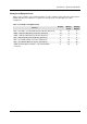
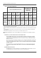
For each database unit you have selected, choose one column from Table 2-1 to specify the database
unit's port usage, and mark the switch settings on the Site Schematic. For example, choose the first
column in the main body of the table (i.e. COM C = RS232/Modem to PC, and COM D = Serial Device) if
the database unit is the first in the chain and communicates with an SMS PC using serial communications.
If only LAN communications is used, either of the next three columns can be selected (either choice is
valid).
Refer to the following sections if you need further information about the communications options.