
Instruction manual


Designing and Planning an M2150 System
10
Access Control Design Guide
Power for Auxiliary Outputs
In most cases, power for auxiliary outputs can be sourced from the controller's internal power supply unit.
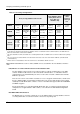
You will need to make sure that the power supply is able to provide sufficient current for all required
devices. The section on page 27 explains how to do this.
If additional current is needed, you will need to order separate power supplies, but note that for sites
requiring UL compliance, all additional power supplies used must be power limited, UL Listed for Access
Control Systems and Accessories.
Cable Supervision for Monitor Points
Monitor points connected to any device other than an ENVS can be supervised for short circuits, open
circuits and tamper conditions, as described on page 31.
Determine the level of cable supervision that is required, mark this on the Site Schematic, and make sure
that the correct resistors are available to the installer.
Planning the Location of Database Units and Controllers
Decide where to install each database unit and controller, and mark this on the Site Schematic. The
devices must be positioned in a location that is accessible for maintenance purposes, and away from
excessive levels of moisture, dust, vibration, heat or electromagnetic interference. Wall-mount and rack-
mount cabinets are available (see page 18).
The section on page 30 gives the maximum cable lengths for all M2150 devices. Carefully plan all cable
routes to database units, controllers, readers, monitor points and auxiliary outputs. Mark the routes on the
Site Schematic, with the cable type to use.
Before finalizing your choices of which database units and controllers to use, check whether there are any
mounting or space limitations that will prevent the use of the larger cabinets and therefore certain
combinations, such as an 8DBC and 8DC in a CAB5.
The first database unit in a chain requires a network, serial or modem connection to an SMS PC. The
proximity of a network socket, telephone socket or PC may influence the location chosen for this database
unit. The maximum length for an RS232 serial cable is 45ft (15m).
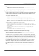
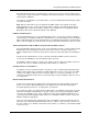
An important feature of controllers is that they can connect to a database unit using a multidrop or star
connection architecture, as shown in Figure 2-1. The maximum distance from a database unit to any
controller must not exceed 3000ft (1km), which means that if the star architecture is used, the distance
between any two controllers could be up to 6000ft (2km). While planning the system, determine suitable
locations for the database units and controllers to keep cable lengths below the maximum allowed.
Database
Unit
Multidrop connections
Star connections
Door/Alarms
Controller
Door/Alarms
Controller
Door/Alarms
Controller
Database
Unit
Door/Alarms
Controller
Door/Alarms
Controller
Figure 2-1: Controller Connection Architecture