
Emulation Probe User's Manual
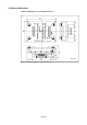
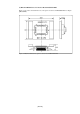
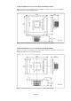

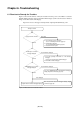
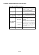
Table Of Contents
- Preface
- Contents
- 1. Precautions for Safety
- 2. Preparation
- 3. Setting Up
- 3.1 Selecting Clock Supply
- 3.2 Using an Internal Oscillator Circuit Board
- 3.3 Using the Oscillator Circuit on the Target System
- 3.4 Using the Internal Oscillator Circuit
- 3.5 Setting Switches
- 3.6 A-D Conversion Bypass Capacitor
- 3.7 Connecting the PC7501
- 3.8 Connecting the Target System
- (1) Connecting to a 100-pin LCC Socket
- (2) Connecting to a 100-pin 0.65-mm-pitch Foot Pattern (Part 1)
- (3) Connecting to a 100-pin 0.65-mm-pitch Foot Pattern (Part 2)
- (4) Connecting to a 100-pin 0.65-mm-pitch Foot Pattern (Part 3)
- (5) Connecting to a 100-pin 0.5-mm-pitch Foot Pattern (Part 1)
- (6) Connecting to a 100-pin 0.5-mm-pitch Foot Pattern (Part 2)
- (7) Connecting to a 100-pin 0.5-mm-pitch Foot Pattern (Part 3)
- (8) Connecting to a 144-pin 0.5-mm-pitch Foot Pattern
- 4. Usage
- 5. Specifications
- 6. Troubleshooting
- 7. Maintenance and Guarantee
( 70 / 76 )
6.3 How to Request for Support
After checking the items in "Chapter 6 Troubleshooting", fill in the text file the installer of the
emulator debugger generates in the following directory and email to your local distributor.
\SUPPORT\product name\SUPPORT.TXT
For prompt response, please specify the following information:
(1) Operating environment
• Operating voltage: X.X [V]
• Operating frequency: XX.X [MHz]
•Clock supply to the MCU: Internal oscillator/External oscillator
• Target system: Connected/Not connected
(2) Condition
• The emulator debugger starts up/does not start up
• The error is detected/not detected in the self-check
• Frequency of errors: always/frequency ( )
(3) Problem