
Emulation Probe User's Manual
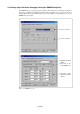
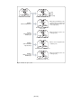
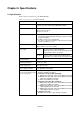
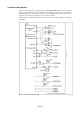
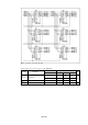
Table Of Contents
- Preface
- Contents
- 1. Precautions for Safety
- 2. Preparation
- 3. Setting Up
- 3.1 Selecting Clock Supply
- 3.2 Using an Internal Oscillator Circuit Board
- 3.3 Using the Oscillator Circuit on the Target System
- 3.4 Using the Internal Oscillator Circuit
- 3.5 Setting Switches
- 3.6 A-D Conversion Bypass Capacitor
- 3.7 Connecting the PC7501
- 3.8 Connecting the Target System
- (1) Connecting to a 100-pin LCC Socket
- (2) Connecting to a 100-pin 0.65-mm-pitch Foot Pattern (Part 1)
- (3) Connecting to a 100-pin 0.65-mm-pitch Foot Pattern (Part 2)
- (4) Connecting to a 100-pin 0.65-mm-pitch Foot Pattern (Part 3)
- (5) Connecting to a 100-pin 0.5-mm-pitch Foot Pattern (Part 1)
- (6) Connecting to a 100-pin 0.5-mm-pitch Foot Pattern (Part 2)
- (7) Connecting to a 100-pin 0.5-mm-pitch Foot Pattern (Part 3)
- (8) Connecting to a 144-pin 0.5-mm-pitch Foot Pattern
- 4. Usage
- 5. Specifications
- 6. Troubleshooting
- 7. Maintenance and Guarantee
( 57 / 76 )
Chapter 5. Specifications
This chapter describes specifications of this product.
5.1 Specifications .............................................................................................................................. 58
5.2 Connection Diagrams .................................................................................................................. 59
5.3 External Dimensions ................................................................................................................... 61
(1) External Dimensions of the Emulation Probe....................................................................... 61
(2) External Dimensions of Converter Board M30800T-PTC ................................................... 62
(3) External Dimensions of Converter Board M3T-F160-100NSD........................................... 63
(4) External Dimensions of Converter Board M3T-FLX-144NSD ........................................... 63