
Emulation Probe User's Manual
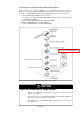
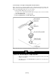

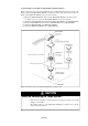
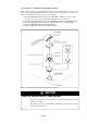

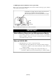
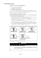
Table Of Contents
- Preface
- Contents
- 1. Precautions for Safety
- 2. Preparation
- 3. Setting Up
- 3.1 Selecting Clock Supply
- 3.2 Using an Internal Oscillator Circuit Board
- 3.3 Using the Oscillator Circuit on the Target System
- 3.4 Using the Internal Oscillator Circuit
- 3.5 Setting Switches
- 3.6 A-D Conversion Bypass Capacitor
- 3.7 Connecting the PC7501
- 3.8 Connecting the Target System
- (1) Connecting to a 100-pin LCC Socket
- (2) Connecting to a 100-pin 0.65-mm-pitch Foot Pattern (Part 1)
- (3) Connecting to a 100-pin 0.65-mm-pitch Foot Pattern (Part 2)
- (4) Connecting to a 100-pin 0.65-mm-pitch Foot Pattern (Part 3)
- (5) Connecting to a 100-pin 0.5-mm-pitch Foot Pattern (Part 1)
- (6) Connecting to a 100-pin 0.5-mm-pitch Foot Pattern (Part 2)
- (7) Connecting to a 100-pin 0.5-mm-pitch Foot Pattern (Part 3)
- (8) Connecting to a 144-pin 0.5-mm-pitch Foot Pattern
- 4. Usage
- 5. Specifications
- 6. Troubleshooting
- 7. Maintenance and Guarantee
( 47 / 76 )
Chapter 4. Usage
This chapter describes from turning on the power of this product to starting up the emulator debugger.
4.1 Turning On the Power ................................................................................................................. 48
(1) Checking the Connection of the Emulator System ............................................................... 48
(2) Turning ON/OFF the Power ................................................................................................. 48
(3) LED Display When the Emulator Starts Up Normally......................................................... 49
4.2 Downloading Firmware ............................................................................................................... 50
(1) When It is Necessary to Download Firmware ......................................................................50
(2) Downloading Firmware in Maintenance Mode ....................................................................50
4.3 Starting Up the Emulator Debugger (Setting the EMEM Dialog Box)....................................... 51
(1) Setting the Debug Monitor Bank Address ............................................................................ 52
(2) Selecting a Processor Mode ..................................................................................................52
(3) Setting Emulation Memory................................................................................................... 53
(4) Emulation Memory Allocation as Expansion Area ..............................................................53
(5) Referring MCU STATUS ..................................................................................................... 55
4.4 Self-check .................................................................................................................................... 55
(1) Self-check Procedure ............................................................................................................55
(2) If an Error is Detected in the Self-check............................................................................... 55