
Emulation Probe User's Manual
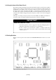
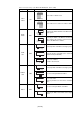
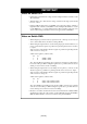
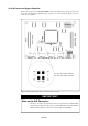
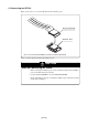
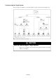
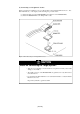
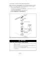
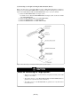
Table Of Contents
- Preface
- Contents
- 1. Precautions for Safety
- 2. Preparation
- 3. Setting Up
- 3.1 Selecting Clock Supply
- 3.2 Using an Internal Oscillator Circuit Board
- 3.3 Using the Oscillator Circuit on the Target System
- 3.4 Using the Internal Oscillator Circuit
- 3.5 Setting Switches
- 3.6 A-D Conversion Bypass Capacitor
- 3.7 Connecting the PC7501
- 3.8 Connecting the Target System
- (1) Connecting to a 100-pin LCC Socket
- (2) Connecting to a 100-pin 0.65-mm-pitch Foot Pattern (Part 1)
- (3) Connecting to a 100-pin 0.65-mm-pitch Foot Pattern (Part 2)
- (4) Connecting to a 100-pin 0.65-mm-pitch Foot Pattern (Part 3)
- (5) Connecting to a 100-pin 0.5-mm-pitch Foot Pattern (Part 1)
- (6) Connecting to a 100-pin 0.5-mm-pitch Foot Pattern (Part 2)
- (7) Connecting to a 100-pin 0.5-mm-pitch Foot Pattern (Part 3)
- (8) Connecting to a 144-pin 0.5-mm-pitch Foot Pattern
- 4. Usage
- 5. Specifications
- 6. Troubleshooting
- 7. Maintenance and Guarantee
( 36 / 76 )
3.7 Connecting the PC7501
Figure 3.9 shows how to connect the PC7501 and the emulation probe.
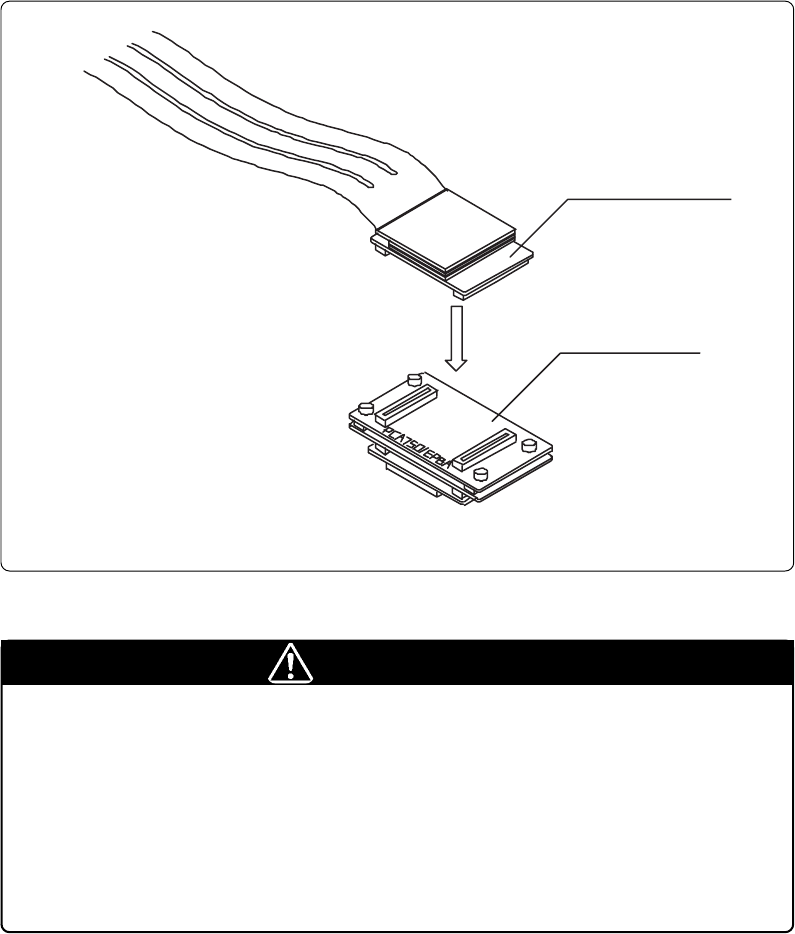
Figure 3.9 Connecting the PC7501 and emulation probe
CAUTION
Note on Connecting the Cable:
• When connecting the emulation probe, be sure to hold the both sides of the emulation
probe horizontally and insert it directly.
•Connect the PCA7501EPBA board to the M3T-FLX160-EPB.
•Always shut OFF power before connecting the emulation probe. Otherwise, internal
circuits may be damaged.
M3T-FLX160-EP
B
M30850T-EPB
Note: Connect the PCA7501EPBA board side to the M3T-FLX160-EPB.