
Emulation Probe User's Manual

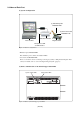

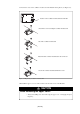
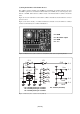
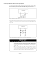
Table Of Contents
- Preface
- Contents
- 1. Precautions for Safety
- 2. Preparation
- 3. Setting Up
- 3.1 Selecting Clock Supply
- 3.2 Using an Internal Oscillator Circuit Board
- 3.3 Using the Oscillator Circuit on the Target System
- 3.4 Using the Internal Oscillator Circuit
- 3.5 Setting Switches
- 3.6 A-D Conversion Bypass Capacitor
- 3.7 Connecting the PC7501
- 3.8 Connecting the Target System
- (1) Connecting to a 100-pin LCC Socket
- (2) Connecting to a 100-pin 0.65-mm-pitch Foot Pattern (Part 1)
- (3) Connecting to a 100-pin 0.65-mm-pitch Foot Pattern (Part 2)
- (4) Connecting to a 100-pin 0.65-mm-pitch Foot Pattern (Part 3)
- (5) Connecting to a 100-pin 0.5-mm-pitch Foot Pattern (Part 1)
- (6) Connecting to a 100-pin 0.5-mm-pitch Foot Pattern (Part 2)
- (7) Connecting to a 100-pin 0.5-mm-pitch Foot Pattern (Part 3)
- (8) Connecting to a 144-pin 0.5-mm-pitch Foot Pattern
- 4. Usage
- 5. Specifications
- 6. Troubleshooting
- 7. Maintenance and Guarantee
( 29 / 76 )
(3) Using the Oscillator Circuit Bare Board
The oscillator circuit board OSC-3 (for 30 MHz) is preinstalled to the emulator main unit. To use it
at 32 MHz, replace the board with the included OSC-3 (for 32 MHz). To use it at a frequency other
than 30 or 32 MHz, build a desired oscillator circuit on the included OSC-2 oscillator circuit bare
board.
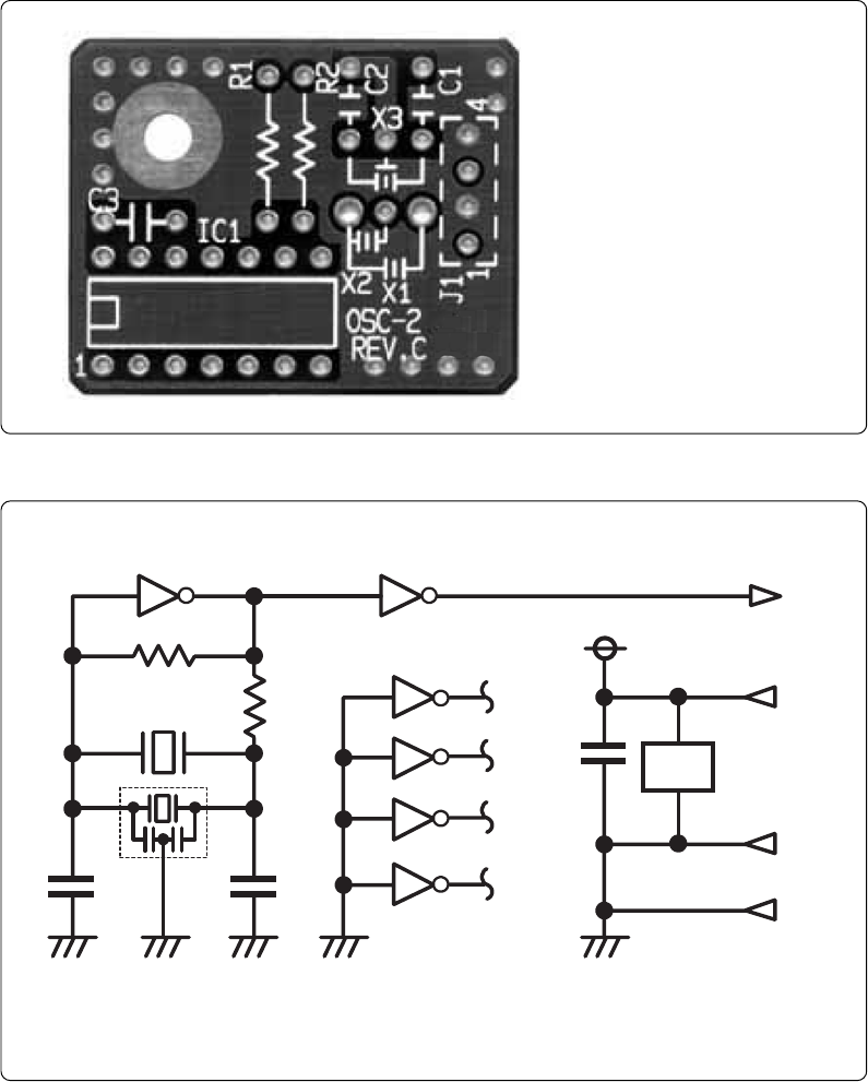
Figure 3.3 shows an external view of the OSC-2 oscillator circuit bare board and where the connector
pins are located.
Figure 3.4 shows the circuitry of oscillator circuit bare board OSC-2. Use the number of oscillator
circuits recommended by the oscillator manufacturer.
Figure 3.3 External view of the oscillator board (OSC-2) and connector pin assignments
J1-4: GND
Figure 3.4 Circuit of the oscillator board (OSC-2)
J1-3: Oscillator output
J1-2: GND
J1-1: Vcc
* X1: 5.08-mm-pitch 2-pin oscillator IC1: Inverter (Unbuffer)
* X2: 2.54-mm-pitch 2-pin oscillator
* X3: 2.54-mm-pitch 3-pin oscillator
IC1
R1
C2
C1
X1 ,X2
CLK
Vcc
GND
R2
J1-3
1011 8
9
2
1
4
3
6
5
12
13
C3
IC1
J1-1
J1-2
J1-4
GND
IC
1
**
X3
*
IC1
14
7